WHYTE Mudguard Assembly Instructions
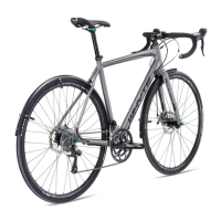
◊ Reference figure E. Us-
ing an M5 x 20 long
cap-screw (22), a
washer with a Ø5 hole
(7) & two 5mm thick
spacers (23), attach
the looped end of the
side-stay (4) to the
threaded hole in the
left front fork leg. For
the threaded hole adja-
cent to the axle, two
spacers (23) are re-
quired to allow the side
-stay (4) to clear the
disc brake caliper (see Terminology). Some other forks have a
t
hreaded hole further up the side of the fork. In this case no
spacers (23) are required.
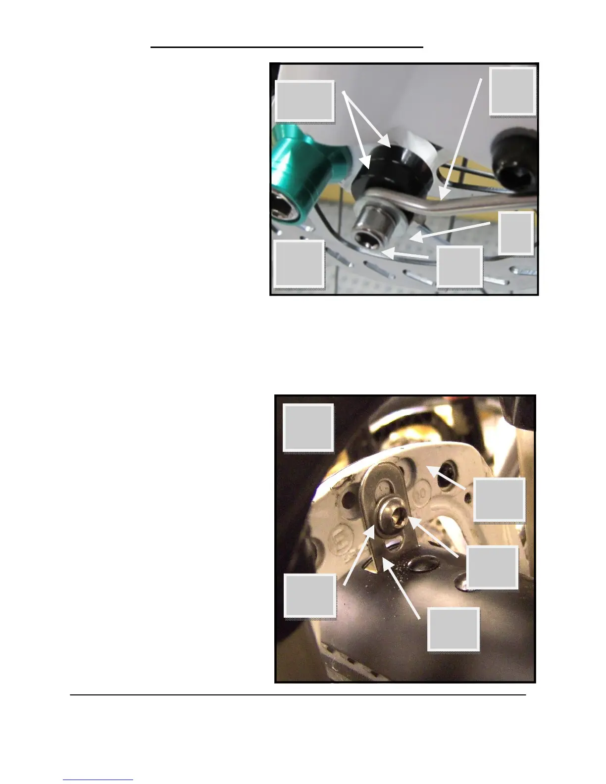
• For Suspension Forks
◊ Reference figure F. Us-
ing an M6 x 12 long
button head cap-screw
(12) and a small wash-
er with a Ø6 hole (9),
attach the bridge
bracket (11) to the rear
of the lower leg bridge
of the front fork (13).
4
22
E
7
23
F
12
11
13
9