2. Design and function
2.1 Overview
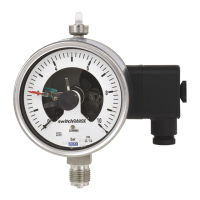
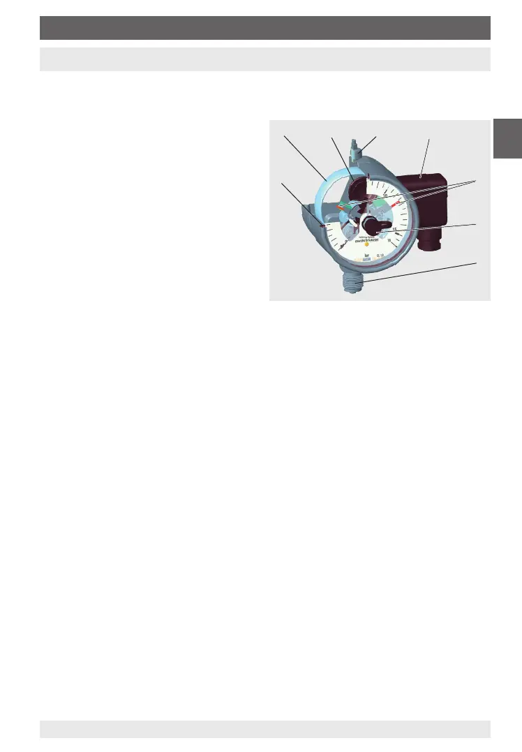
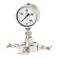
Example, model PGS23.100, version “S1” per EN 837
Laminated safety glass
Pressure element
Plug of the blow-out device
Pressure compensating valve
Electrical connection with cable box
Set pointer
Adjustment lock
Process connection
2.2 Description
These pressure gauges with inductive
contact(s) have been designed speci-
cally for applications in hazardous areas.
WIKA manufactures and qualies these instruments following EN 837 (gauge pressure),
DIN 16002 (absolute pressure), DIN 16003 (dierential pressure) and DIN 16085 (switch
contacts) in the versions “S1” and “S3”.
Version “S1” per EN 837
This version is designed with a blow-out device at the case.
Safety version “S3” per EN 837
This version is made up of laminated safety glass, a solid bae wall between measuring
system and dial and a blow-out back. In the event of a failure, the operator is protected at the
front side, as media or components can only be ejected via the back of the case.
Switch contact model 831
The built-in electrical inductive contacts are non-contact slot-type inductive proximity
sensors, which are powered from switching ampliers with certied intrinsically safe circuits.
On exceeding the adjustable limit values, their output circuits are either opened or closed.
2.3 Scope of delivery
Cross-check scope of delivery with delivery note.
5Pressure gauges with inductive contact model 831, for hazardous areas
14320154.01 06/2019 EN/DE
EN
2. Design and function