2 of 9
1. GENERAL NOTES
1.1 FOREWORD
The wrong choice of a models or a version, as well as the
incorrect installation, lead to malfunction and reduce instrument
life. Failure to follow the indications given in this manual can
cause damage to the instrument, the environment and persons.
1.2 ALLOWED OVERRANGE
Pressures exceeding the working range can be occasionally
tolerated provided they remain within the limits stated in the
instrument features (vacuum or proof pressure). Continuous
pressures exceeding the working range can be applied to the
instrument, provided they are clearly stated in the instrument
features. The current and voltage values stated in the technical
specifications and ratings must not be exceeded. Transitory
overranges can have a destructive effect on the switch.
1.3 MECHANICAL VIBRATIONS
Can generally lead to the wearing of some parts of the instrument
or cause spurious action. It is therefore recommended that the
instrument be installed in a place where there are no vibrations.
In cases where this is impossible it is advisable to take measures
to lessen the effects (elastic supports, installation with the pin of
the microswitch positioned at right angles to the vibration plane,
etc.).
1.4 TEMPERATURE
Due to the temperature of both the environment and the process
fluid, the temperature of the instrument could exceed the allowed
limits (normally from -40° to +60°C). Therefore, in case it does,
suitable measures (protection against heat radiation, fluid
separators, cooling coils, heated lockers) must be taken. The
process fluid or its impurities must not in any case solidify inside
the instrument chambers
2. OPERATING PRINCIPLE
The differential pressure, acting on the sensitive diaphragm
element, determines its elastic deformation which is used to
actuate one or two electric microswitches adjusted at set point
values. The microswitches are of the snap acting type with
automatic reset. When the pressure moves away from the set
values, returning towards the normal values, the switch is reset.
The dead band (difference between the set point value and the
reset value) can be set or adjustable (letter R in the contact
codes).
3. MODEL CODE
See Annex 1
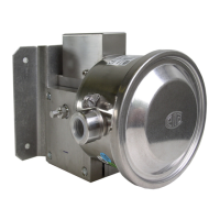
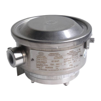
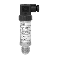
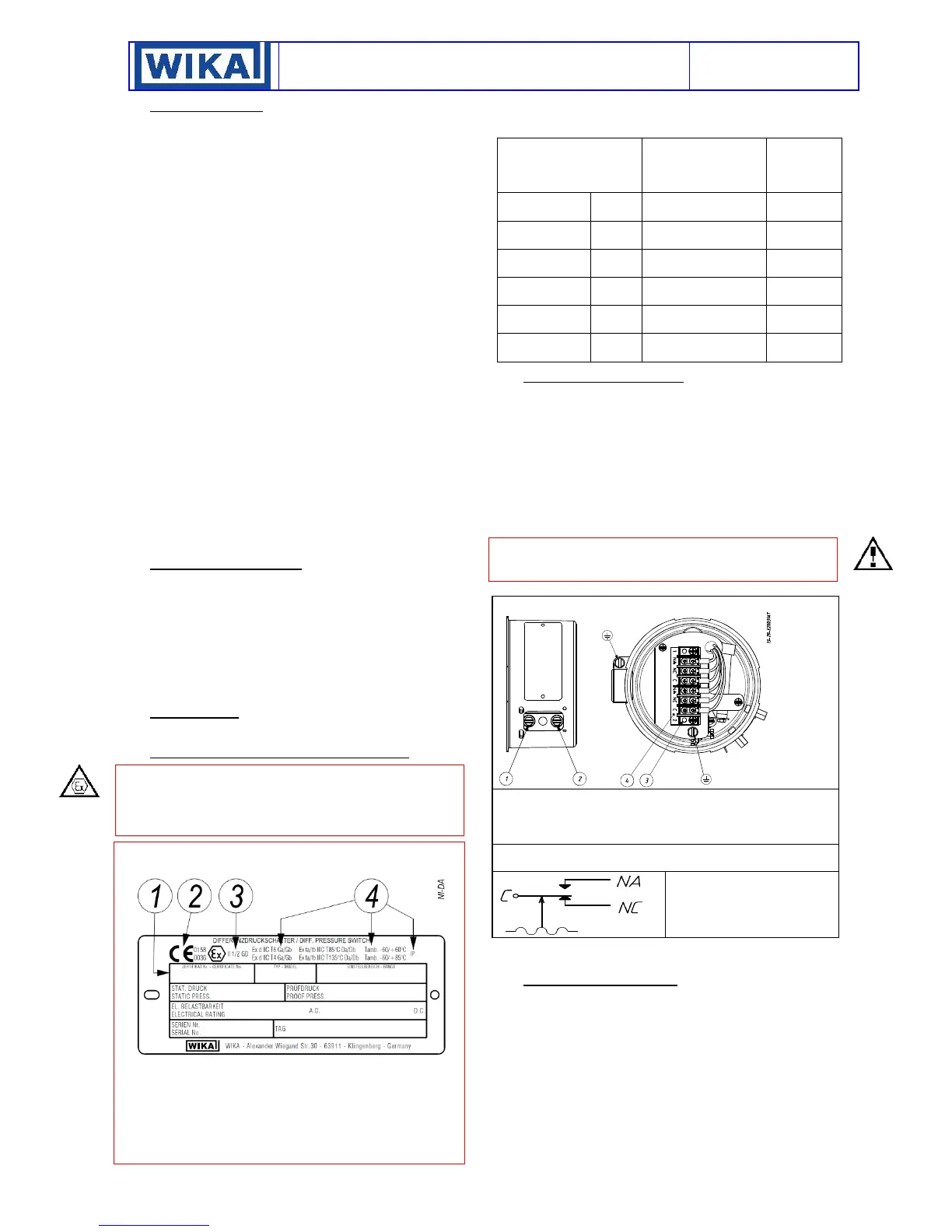
4. IDENTIFICATION PLATE AND MARKINGS
The instrument is fitted with a metal plate bearing all its functional
characteristics and in case of flameproof or intrinsic safety
execution also the markings prescribed by standard IEC/EN
60079-0. Fig.1 shows the plate mounted on flameproof
instruments.
5. SET POINT REGULATION
Each microswitch is independent and can be adjusted by means
of a screw (for adjustment) to snap when the pressure reaches
(increasing or decreasing) the desired value (set point). The
instrument is usually supplied with the switches adjusted at the
setting range value nearest to zero (factory calibration). The
instrument is supplied with a label showing the set point
calibration value. With factory calibration the values are not
indicated, as these are temporary and will be modified with the
definitive values. Prior to installation the instrument must be
calibrated and the definitive calibration values written on the
label.
If the instrument has been ordered with a specific calibration,
check the calibration values marked on the relevant label, prior
to installation.
The position of the adjustment screw is given in figure 2.
The effect that the direction of rotation of the adjustment screw
has is described on the label.
6. SET POIT CALIBRATION
In order to proceed with the calibration and the periodical
functional verification of the instrument a suitable calibration
circuit (Fig. 3) and an adequate pressure source is required. The
test instrument should have a measurement range approximately
equal to or slightly wider than the pressure switch range and
should have an accuracy consistent with the accuracy required
to calibrate the set point.
 Loading...