GB
11258421.0901/2012GB/D
32 WIKAoperatinginstructionstemperaturetransmitterT32.xS
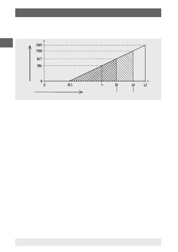
Maximumpermissibleloaddependingonthesupplyvoltage:
Load diagram
11289130.02
VoltageUBinV
LoadRAinΩ
Exia ExnA/nL/ic
Forthepowersupply,useanenergy-limitedelectricalcircuit(EN/UL/
IEC61010-1,section8.3)withthefollowingmaximumvaluesforthe
powersupply:
forU
B
=42V(DC):5A
Fortheexternalpowersupplyaseparateswitchisrequired.
9.2 HART
®
loop display (DIH50)
AdditionalcongurationofthetemperaturetransmitterwithaHART
®
LoopDisplay(modelDIH50)ispossible.Thisisusedforthelocal
displayofthecurrentprocessvalue.Theunitandthecongured
measuringrangeofthetransmitterareautomaticallyupdatedvia
theHART
®
protocolinthedisplay.NofurtherchangeoftheHART
®
loopdisplay(DIH50)isnecessary.Todothis,theDIH50mustbein
HART
®
mode.
9. Electrical connections
 Loading...