18 MONTEREY TOP VENT GAS WALL HEATER
ORIFICE SIZES
The efficiency rating of this appliance is a product thermal
efficiency rating determined under continuous operating
conditions and was determined independently of any
installed system. For elevations above 2,000 feet, reduce
ratings 4% for each 1,000 feet above sea level.
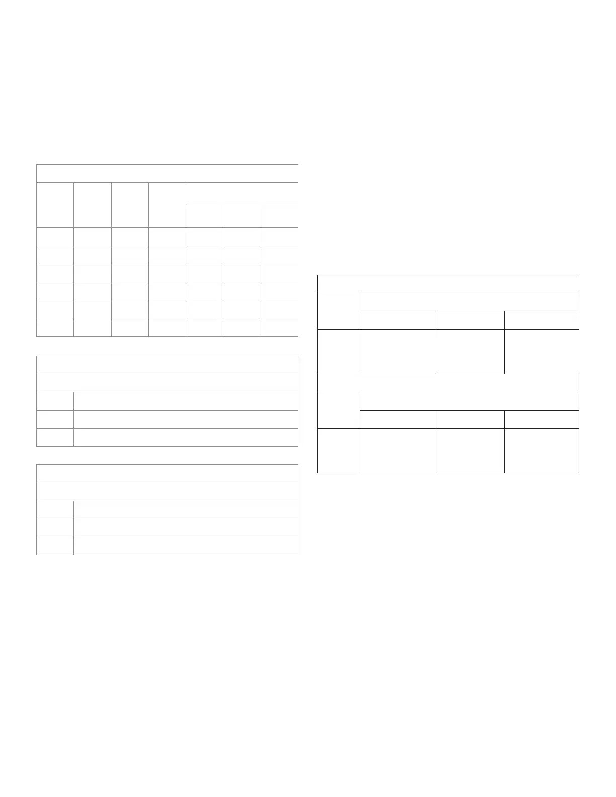
FURNACE TECHNICAL INFORMATION
MODEL
NUMBER
GAS
TYPE
INPUT
RATING
BTU/hr.
HEATING
CAPACITY
RATING
BTU/hr.
MAIN BURNER ORIFICE
DRILL DECIMAL
QUANTITY
2509622A NATURAL 25,000 18,935 #43 0.089 1
2509621A PROPANE 25,000 19,759 .057" 1
3509622A NATURAL 35,000 34,496 #36 0.106 1
3509621A PROPANE 35,000 25,588 .069" 1
5009622A NATURAL 50,000 38,490 .091" 2
5009621A PROPANE 50,000 39,827 .058" 2
GAS CONVERSION KITS
NATURAL GAS TO PROPENE GAS
8913 25096A SERIES WITH WILLIAMS BRAND GAS VALVE
8914 35096A SERIES WITH WILLIAMS BRAND GAS VALVE
8909 50098 SERIES WITH WILLIAMS BRAND GAS VALVE
GAS CONVERSION KITS
PROPANE GAS TO NATURAL GAS
8915 25096A SERIES WITH WILLIAMS BRAND GAS VALVE
8916 35096A SERIES WITH WILLIAMS BRAND GAS VALVE
8912 50098 SERIES WITH WILLIAMS BRAND GAS VALVE
GAS PIPING
The gas supply line must be of adequate size to handle the
Btu/hr. requirements and length of the run for the unit being
installed.
Determine the minimum pipe size from Figure 13, based on
the length of the run from the gas meter to the unit.
All piping must comply with local codes and ordinances
or with the National Fuel Gas Code (ANSI Z223.1 NFPA No.
54), whichever applies. (In Canada: CAN/C.GA B149). Refer
to FIGURE 14 for the general layout of the unit. It shows the
basic fittings needed.
The following rules apply:
1. Use new, properly reamed steel or black iron pipe and
fittings free of metal chips and debris that are approved by
local codes. Metal chips and debris can damage the valve.
FIGURE 13 PIPE CAPACITY
PIPE CAPACITY BTUhr. WITH FITTINGS
NATURAL GAS
LENGTH
OF PIPE
FEET
PIPE SIZE
1/2”
3/4” 1”
20
40
60
92,000
63,000
50,000
190,000
130,000
105,000
350,000
245,000
195,000
PROPANE
LENGTH
OF PIPE
FEET
PIPE SIZE
1/2”
3/4” 1”
20
40
60
189,000
129,000
103,000
393,000
267,000
217,000
732,000
504,000
409,000
INSTALLING YOUR FURNACE
2. Do not thread pipe too far. Valve distortion or malfunction
may result from excess pipe within the gas control valve.
Apply a moderate amount of good quality dope to the
pipe only. Leave the two end threads bare. Figure 15
3. Use ground joint unions.
4. Install a drip leg (sediment trap) to trap dirt and moisture
before it can enter the gas valve. The nipple must be a
minimum of 3-inches long.
5. Install a manual shutoff valve.
6. Provide a 1/8” NPT test gauge connection immediately
before the gas supply connection to the furnace.
GAS CONNECTION
If the installation is for propane gas, have the propane installer
use a two stage regulator and make all the connections from
the storage tank.
Use two pipe wrenches when making the connection to the
valve to prevent turning and/or damage to the valve.
Connections between the manual shutoff valve and burner
control assembly can be made with an A.G.A./C.G.A. design
certified flexible connector if allowed by local codes. Drip leg
and ground joint unions are still required.
Tighten all joints securely.
Test all piping for leaks. When checking gas piping to the
furnace with gas pressure less than 1/2 PSI, shut off manual
gas valve to the furnace. If gas piping is to be checked with
the pressure at or above 1/2 PSI, the furnace and manual
shutoff valve must be disconnected during testing. (SEE
WARNING). Apply soap solution (or a liquid detergent) to
each joint. Bubbles forming indicate a leak. Correct even the
slightest leak at once.