30 WILOSE04-2015V05DINA4
English PRODUCT DESCRIPTION
Pushbuttons and LEDs on the housing are used
to operate the switchgear, display the operating
state,andsignalfaults.Thehousingcovermust
not be opened during operation.
DANGER due to electrical voltage!
There is arisk of fatal electric shocks oc-
curring when performing work on the open
switchgear. Only operate the switchgear with
the cover closed!
2.5. Standards and guidelines used
The switchgear is subject to various European
directives and harmonised standards. See the EC
declaration of conformity for precise information
about these.
Also,variousregulationsareusedasabasis
for operating, installation and dismantling the
switchgear.
2.6. CE marking
The CE marking is attached to the rating plate.
3. Product description
The switchgear has been manufactured with
great care and is subject to constant quality con-
trols. Trouble-free operation is guaranteed if it is
installed and maintained correctly.
3.1. Intended use and elds of application
DANGER - explosive atmosphere!
If the connected pump and signal transmitter
are used in potentially explosive areas, there
is adanger of fatal injuries from explosions!
Theconnected pump and signal transmitter
must always be used outside of potentially
explosive areas. Installation must always be
carried out by aqualied electrician.
The MS-Lift switchgear is designed for
• automaticcontrolof2nonEx-ratedpumpsin
lifting units and sewage chambers for water/sew-
age conveyance.
The switchgear must not
• beinstalledinpotentiallyexplosiveareas.
• beooded.
Intended use also includes observation of these
instructions. Any other use is considered to be
outside the intended use.
NOTE
Forautomaticcontrol,oatswitchesmustbe
provided by the customer.
3.2. Set-up
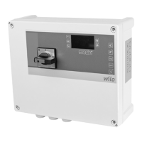
Fig. 1.: Overview of operating components
1 Main switch 3
Control panel with
buttons
2 LED indicators
The switchgear comprises the following main
components:
• Mainswitch:forswitchingtheswitchgearon/off
NOTE
• The"S"versionhasnomainswitch.Aplugis
pre-assembled instead.
• The"O"versionhasnomainswitchandnoplug.
Acorrespondingmainsdisconnectionfacility
must be provided by the customer in accord-
ance with the local regulations.
• LEDs for displaying the current operating state
(operation/fault)
• Automatic mode
• Pump operation
• High water
• Service interval indicator
• Overload fault
• Winding fault
• Monitoring of certain operating parameters
(version S only)
• Control panel with buttons
• Manual mode for each pump
• Stop
• Automatic mode
• Buzzer OFF/reset
• Contactor combinations for connecting up pumps
during direct starting, including electronic trig-
geringforexcesscurrentprotection
3.3. Function description
The microcontroller-controlled Micro Control
switchgearisdesignedforcontroloftwoxed
speed pumps with level-dependent switching.
Levelmeasurementisviaatwo-positioncontrol
withaoatswitchforeachpump,whichneeds
tobeprovidedbythecustomer.Thepumpis
activated/deactivated automatically depending
onthelllevel.Ifafollow-uptimeisrequired,
thiscanbesetviaapotentiometer.Pumpcycling
is carried out after every pumping procedure.
Onreachinghigh-waterlevel(detectedviaasep-
arateoatswitch),avisualandaudiblewarningis
emitted and forced switch-on of the pumps takes
place.Thecollectivefaultsignal(SSM)isactive.
The current operating state is indicated via LEDs
on the front side. Operation is via 5 pushbuttons
onacontrolpanelattachedattheside.
Faults are indicated visually via LEDs and audibly
viaanintegratedbuzzer.Thelasterrorisstoredin
the fault memory.
3.4. Technical data
3.4.1. Inputs
• 3digitalinputsforoatswitches(pumpbaseload
on/off, pump peak load on/off, high water)
• 2 inputs for thermal winding monitoring with
bimetallic temperature sensor. Connection of PTC
sensors is not possible!
3.4.2. Outputs
• 1 potential-free contact for SSM
 Loading...