15
same time, installation should be
carried out such that any leaking
water cannot drop onto the control
module, align upper slide valve
laterally.
– Carry out off-load installation
with the pump motor lying hori-
zontally. Mounting positions for
the module see fig. 3. Other
mounting positions on request.
– An arrow on the pump casing
indicates the direction of flow
(fig. 4, Pos.1).
– When screwing the pump into the
pipework the pump can be secu-
red with a spanner against turning
at the appropriate points (fig. 5).
– If the mounting position of the
module is to be changed, the
motor casing must be rotated as
follows:
– Unscrew 2 Allen screws on
pump casing,
– Rotate motor casing, including
control module,
Be careful
not to dama-
ge the seal. Seal size:
l 86x l 76 x 2.0 mm EP
– Tighten Allen screws,
– For units which
are to be insu-
lated, only the pump housing may
be insulated. The motor and the
condensation water holes must
remain free from all blockages (Fig.
4, pos.2).
ATTENTION!
ATTENTION!
ENGLISH
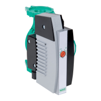
– Setting (fig. 1, pos. 2)
auto = automatic operation
„ON“
= automatic operation
„OFF“
– Setting range (fig.2):
E... / 1 - 3: H
min
= 0.5 m,
H
max
= 3.0 m.
E... / 1 - 5: H
min
= 1.0 m,
H
max
= 5.0 m.
4.2 Products delivered
– Heat circulating pump complete,
– Installation and operating
instructions
5 Assembly/Installation
5.1 Assembly
– The pump should only be instal-
led once all welding and solde-
ring work is complete and the
pipework has if necessary been
thoroughly flushed.
– Install the pump in an easily
accessible place, so it can easily
be inspected or replaced.
– When installing flow pipes in open
units, the expansion flow pipe
must branch off before the pump.
– Shut-off valves should be fitted
before and after the pump to
facilitate replacement. At the
 Loading...