9WILO SE 09/2009
English
ATTENTION! The pump must not run dry.
Warranty does not cover damages to the pu mp
due to dryrunning.
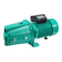
4.1 Description of WJ-Series Pump
Series WJ pumps are portable for mobile applica-
tion. Single phase pumps have a carrying grip and
are supplied complete with power cable, plug
and ON/OFF switch.
Standard-Installations
– Figure 1: Pump in suction
– Figure 2: Pump under pressure on storage tank or
on town water supply with dry-running prote-
ction system.
Legend for Installation samples (see figures 1 and 2):
Pos. 1 Strainer-foot valve (maximum passing
section 1 mm)
Pos. 2 Pump suction valve
Pos. 3 Pump discharge valve
Pos. 4 Non-return valve
Pos. 5 Filling plug
Pos. 6 Draining plug
Pos. 7 Pipe supports
Pos. 8 Strainer
Pos. 9 Storage tank
Pos. 10 Town water supply
Pos. 11 3~ motor protection relay
Pos. 12 OFF/ON switch for single phase motor
(red indicator light)
Pos. 13 Power plug (1~ -Motor)
4.2 Scope of supply
– Jet Pump (WJ)
– Installation and Operation instructions.
4.3 Accessories
– Suction kit,
– Isolating valves,
– Non-return valves,
– Strainer-foot valve,
– Bladder tank,
– Vibrationless sleeves,
– Motor protection relay,
– Dry running protection (ME kit),
– On-off control device...
The use of new accessories is recommended.
5. Sitting/lnstallation
5.1 Installation
The pump must be operated in strict compliance
with local water supply regulations.
Requirements on installation location:
– easy to reach
– well vented, dry and frostfree
– Installation on a concrete socket or directly on a
smooth and horizontal floor.
lt is the Operators responsibility to take all pre-
ventive measures (e. g. provision of alarm
systems, standby pump, etc.) to avoid conse-
quential damages such as flooding due to pump
failure.
– Suction and discharge piping to be provided on
site by others.
– When using solid pipe connections the pump
must be firmly fixed to the floor.
– If not firmly fixed, flexible connectors must at
least be used for suction and discharge ports.
– The suction pipe must be fully airtight and be
installed free of stress, steadily rising towards the
pump.
– Suction lifts above 5 metres require a suction
pipe size of not less than 1
1/4
”.
– Discharge pipe connections must be free of
stress on the pump.
ATTENTION! In order to ensure proper operation
a static discharge head of 30 cm is required; the
discharge pipe must thus be installed with a rise
of at least 30 cm.
– A foot valve is required at the end of the suction
line. lt must be located not less than 30 cm below
the lowest water level. Recommended is the use
of a suction hose set (optional extra) consisting
of suction hose, suction strainer and foot valve.
5.2 Electrical connection
ATTENTION! All electrical work to be carried out
by a qualified and locally licenced electrician in
strict conformity with locally ruling regulations.
30 mA earth fault circuit interruptors should be
used for the electrical circuits to the pump.
– Regulations of VDE 0100, Part 702 must be
observed for use in conjunction with swimming
pools or garden ponds.
– Electrical plug connections must be made in
flood-safe locations and be protected from moi-
sture.
– Check available power supply.
– Take note of pump name plate data require-
ments.
– Supply side fuse: 10A, inert action.
– Observe local earthing requirements.
Pumps must only be operated on electrical cables
(also extension leads) conforming with local
ruling standards.
– Three-phase motors to be wired in accordance
with Fig. 3 (motor terminal wiring).
– Three-phase motors require the onsite provision
and installation by others of an external thermal
overload protection device to be set to the F.L.C.
value stated on the motor name plate.
– Do not forget to connect the earth.
– A connection error would damage the motor.
– The power cable must never touch the pipe or
the pump ; make sure that it is sheltered from
any humidity.
6. Commissioning
– Check to ensure that a sufficiently high water
level is available in the open break tank or bore.
Dry-running of the pump must be prevented as it
will lead to destruction of the mechanical seal.
– Fill pump and suction line via the fill plug. Only a
filled pump has self-priming capacity.
– Open discharge isolating valve(s) to allow free air
evacuation from the suction pipe.
– Three-phase motors require a rotation check:
Briefly switch on the pump and check whether
actual direction of rotation corresponds with the
 Loading...