Installation and electrical connection en
Installation and operating instructions Wilo Motor T 17.3, 20.2:, EMU FA, Rexa SUPRA, Rexa SOLID 73
6.5.2.1 Checking the insulation resistance
of the motor winding
Use an insulation tester to measure the insulation resistance (measuring
voltage=1000V). Observe the following values:
ƒ At the time of initial commissioning: Insulation resistance may not be less than
20MΩ.
ƒ For further measurements: Value must be greater than 2MΩ.
6.5.2.2 Test the resistor of the temper-
ature sensor
Measure the resistor of the temperature sensors with an ohmmeter. The following
measured values must be complied with:
ƒ Bimetallic strip: Measured value = 0ohms (continuity).
ƒ PTC sensor (PTC thermistor): Measured value depends on the number of sensors in-
stalled. A PTC sensor has a cold resistance range of 20to 100ohms.
– With three sensors in series, the measured value range is from 60 to 300ohms.
– With four sensors in series, the measured value range is from 80 to 400ohms.
ƒ Pt100 sensor: Pt100 sensors have a resistance value of 100ohms at 0°C (32°F).
Between 0°C (32°F) and 100°C (212°F), the resistance increases by 0.385ohms per
1°C (1.8°F) increase.
At an ambient temperature of 20°C (68°F), the resistance is 107.7ohms.
6.5.3 Asynchronous motor power con-
nection
The three-phase current version is supplied with bare cable ends. Connection to the
mains is made by connecting the connection cables in the switchgear. Refer to the at-
tached connection diagram for more precise details regarding the connection. Electrical
connection must always be carried out by a qualified electrician!
NOTICE!The individual wires are designated according to the connection diagram.
Do not cut the wires! There is no additional assignment between the wiring diagram
and connection diagram.
Wiring diagram of the power connections for direct starting
U, V, W
Mains connection
PE (gn-ye)
Earth
Wiring diagram of the power connections for star-delta starting
U1, V1, W2
Mains connection (start of winding)
U2, V2, W2
Mains connection (end of winding)
PE (gn-ye)
Earth
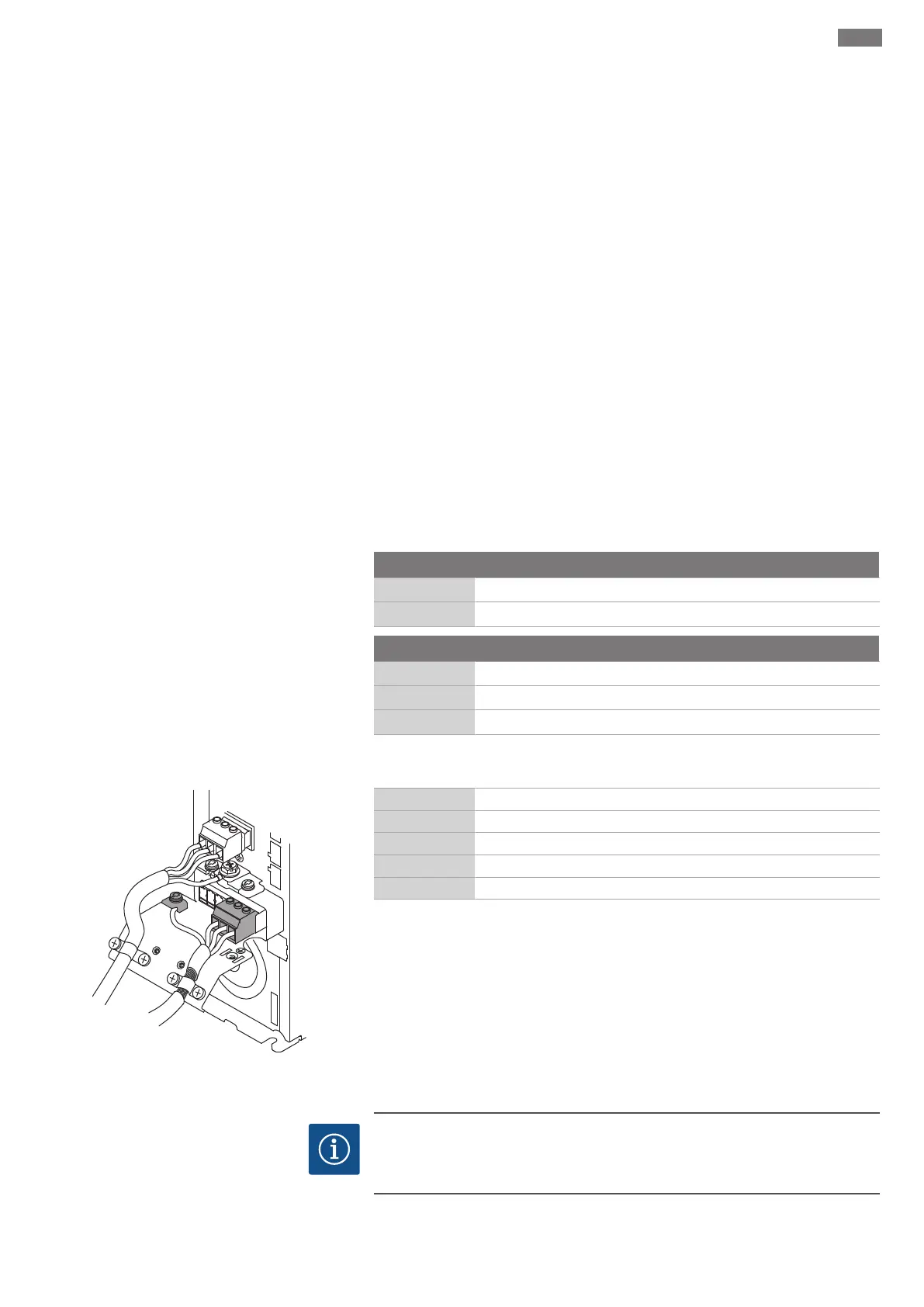
6.5.4 Permanent magnet motor power
connection
Wilo-EFC frequency converter
+DC
BR-
B
M A I N S
L1 L2 L3
91 92 93
99
U V W
MOTOR
99
Fig.9: Pump connection: Wilo-EFC
Terminal Wiring diagram
96 U
97 V
98 W
99 Earth (PE)
Insert the motor connection cables into the frequency converter through the threaded
cable gland. Connect the wires as per the connection diagram.
NOTICE!Widely position cable shielding!
6.5.5 Digital Data Interface connection
NOTICE
Note the instructions for the Digital Data Interface!
Read the separate instructions for the Digital Data Interface and comply with them.
 Loading...