en Installation and electrical connection
74 WILO SE 2019-10
Description
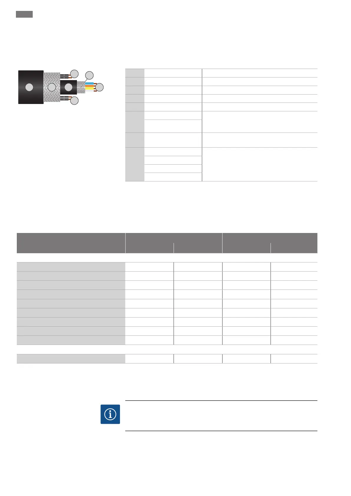
A hybrid cable is used as the control cable. The hybrid cable merges two cables in one:
ƒ Signal cable for control voltage and winding monitor
ƒ Network cable
Fig.10: Hybrid cable diagram
Pos. Wire no/colour Description
1 Outer cable sheath
2 Outer cable shielding
3 Inner cable sheath
4 Inner cable shielding
5
1 = + Connection wires for Digital Data Interface power
supply. Operating voltage: 24VDC (12-30V FELV,
max. 4.5W)
2 = -
6
3/4 = PTC PTC sensor connection wires in the motor winding.
Operating voltage: 2.5 to 7.5VDC
7
White (wh) = RD+ Prepare the network cable and install the supplied
RJ45 plug.
Yellow (ye) = TD+
Orange (og) = TD-
Blue (bu) = RD-
The connection of the Digital Data Interface depends on the selected system mode and
other system components. Note installation suggestions and connection variants in the
instructions for the Digital Data Interface.
NOTICE!Widely position cable shielding!
6.5.6 Monitoring equipment connection
Overview of monitoring devices
Asynchronous motor Permanent magnet motor
T20.2 T20.2 T17.3...-P T20.2...-P
Internal monitoring devices
Digital Data Interface
− • • •
Motor winding: Bimetallic strip
• − − −
Motor winding: PTC
o • (+ 1...3x Pt100) • (+ 1...3x Pt100) • (+ 1...3x Pt100)
Motor bearings: Pt100
o o o o
Sealing chamber: conductive sensor
− − − −
Sealing chamber: capacitive sensor
− • • •
Leakage chamber: Float switch
• − − −
Leakage chamber: capacitive sensor
− • − •
Vibration sensor
− • • •
External monitoring devices
Sealing chamber: conductive sensor
o − − −
• = Standard, − = Not available, o = Optional
All the monitoring devices fitted must always be connected!
Motor with Digital Data Interface
NOTICE
Note the instructions for the Digital Data Interface!
Read the separate instructions for the Digital Data Interface and comply with them.
The Digital Data Interface evaluates all available sensors. Use the graphical user inter-
face of the Digital Data Interface to display current values and set the limit parameters.
A warning message or alarm signal is output upon exceeding the limit parameters. The
motor winding additionally features PTC sensors to enable secure pump deactivation.
 Loading...