English
Installation and operating instructions Wilo-VeroLine-IP-E, VeroTwin-DP-E 85
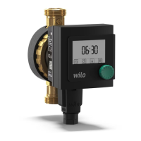
8.6.4 Changing selection/settings To change a setpoint or a setting, generally proceed as follows (for an
example, see Fig. 35):
• Navigate to the desired “Selection/settings” menu element.
The current value or state of the setting and the associated symbol
are displayed.
• Press the red button. The symbol representing the setpoint or the
setting flashes.
• Turn the red button until the desired setpoint or setting is displayed.
For an explanation of the settings represented by the symbols, see
the table in chapter 8.7 “Menu elements reference” on page 87.
• Press the red button again.
The selected setpoint or setting is confirmed, and the value or symbol
stops flashing. The display is back in menu mode with the menu num-
ber unchanged. The menu number flashes.
NOTE:
When values are changed under <1.0.0.0>, <2.0.0.0> and <3.0.0.0>,
<5.7.7.0> and <6.0.0.0>, the display jumps back to the status page
(Fig. 36).
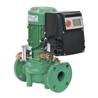
8.6.5 Calling up information
Changes cannot be made in “Information” menu elements. These are
identified on the display by the default “access disable” symbol. To
call up current settings, proceed as follows:
• Navigate to the desired “Information” menu element (<4.1.1.0> in the
example).
The current value or state of the setting and the associated symbol
are displayed. Pressing the red button has no effect.
• Turn the red button to access the “Information” menu elements in the
current sub-menu (see Fig. 37). For an explanation of the settings
represented by the symbols, see the table in chapter 8.7 “Menu ele-
ments reference” on page 87.
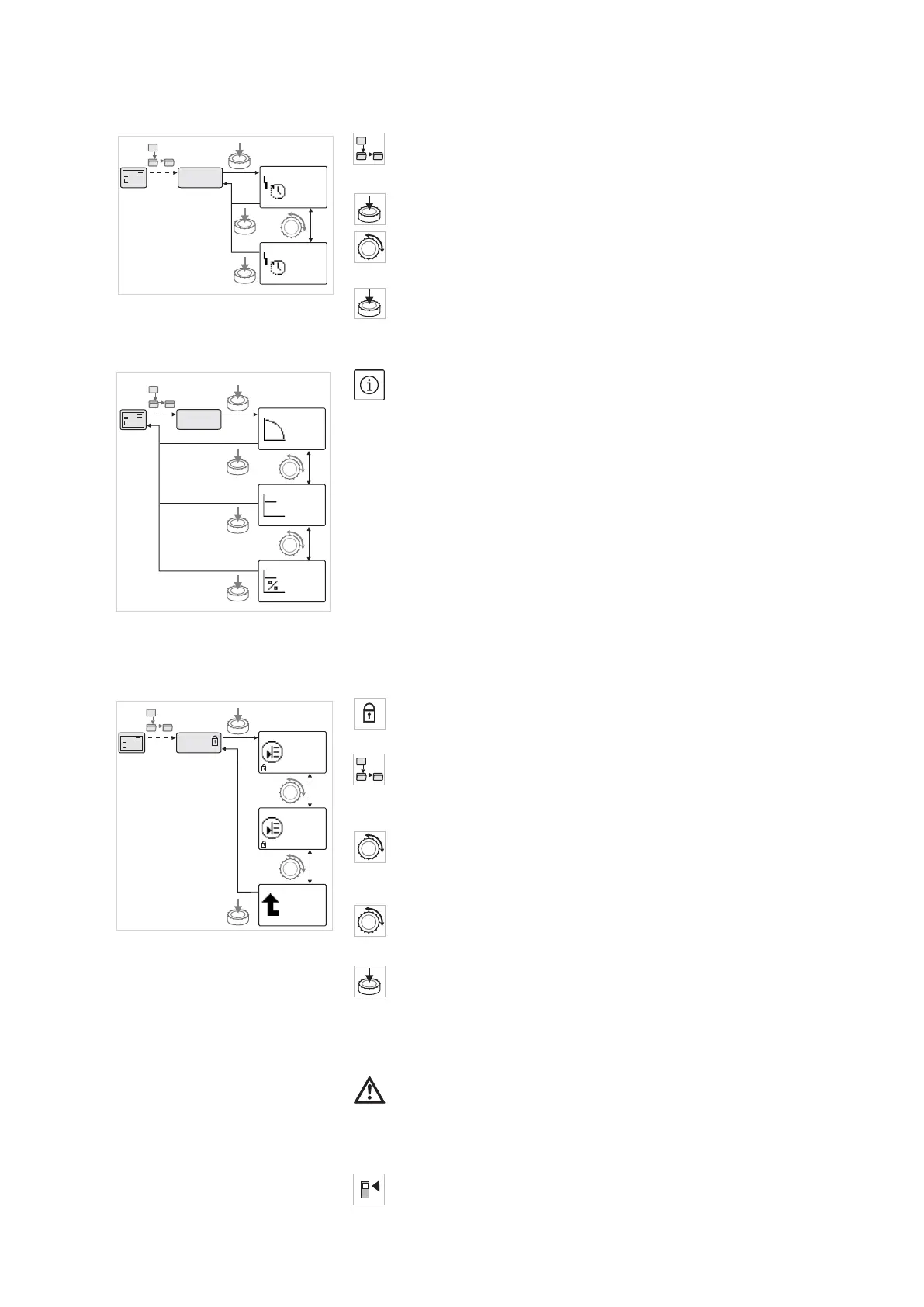
• Turn the red button until the “One level up” menu element is dis-
played.
• Press the red button.
The display returns to the next higher menu level (<4.1.0.0> here).
8.6.6 Activating/deactivating service
mode
Additional settings can be made in service mode. The mode is acti-
vated or deactivated as follows.
CAUTION! Risk of property damage!
Improper setting changes can lead to pump operation errors, which
can lead to material damage to the pump or system.
• Settings in service mode should only be made during commission-
ing and only by qualified personnel.
• Set DIP switch 1 to the ON position.
Fig. 35: Setting with return to the “Selec-
tion/settings” menu element
5.6.3.0
5.6.3.0
S
S
300
10
5.6.3.0
±
12.3
Fig. 36: Setting with return to the status
page
2.0.0.0
2.0.0.0
2.0.0.0
2.0.0.0
±
12.3
Fig. 37: Calling up information
4.1.0.0
4.1.1.0
H/m
P/W
5,4
320
4.1.3.0
12.3
ON
1