English
Installation and operating instructions Wilo-VeroLine-IP-E, VeroTwin-DP-E 91
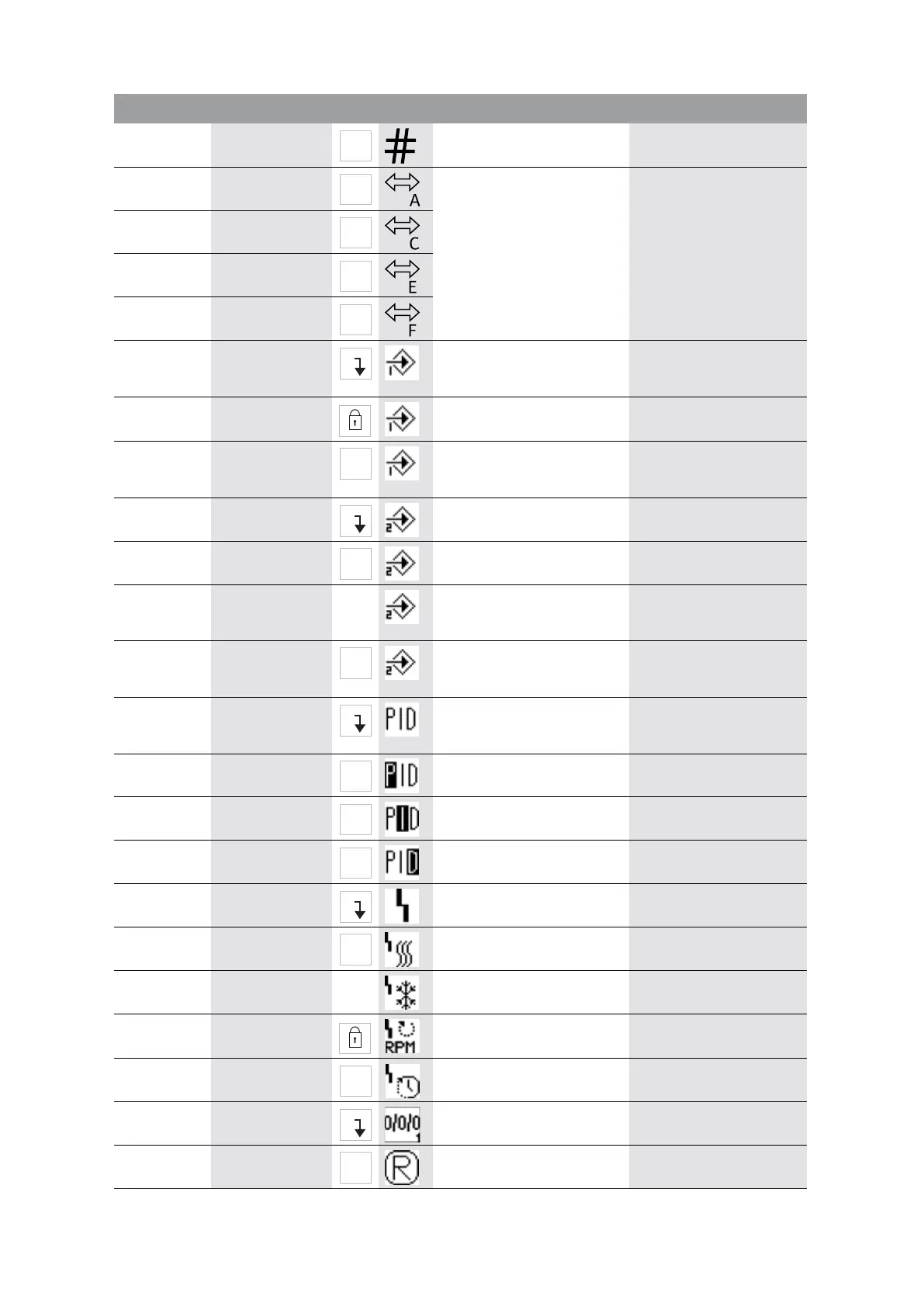
5.2.3.0 Bus address Setting of bus address
5.2.4.0 IF gateway val A
Specific settings of the IF-Mod-
ule, depends on protocol type
Further information can be
found in the installation and
operating instructions of the
IF-Modules.
5.2.5.0
IF gateway val C
5.2.6.0 IF gateway val E
5.2.7.0 IF gateway val F
5.3.0.0 In1 (sensor input) Settings for sensor input 1 Not displayed in the manual
control mode (incl. all sub-
menus)
5.3.1.0
In1 (sensor value
range)
Display of sensor value range 1
Not displayed with PID control
5.3.2.0 In1 (value range) Setting of the value range
Possible values: 0...10 V/2...10 V/
0...20 mA/4...20 mA
5.4.0.0 In2 Setting for external setpoint
input 2
5.4.1.0 In2 active/inactive ON
External setpoint input 2 active
OFF
External setpoint input 2 inac-
tive
5.4.2.0 In2 (value range) Setting of the value range
Possible values: 0...10 V/
2...10 V/0...20 mA/4...20 mA
Not displayed when In2 =
inactive
5.5.0.0
PID parameters Settings for PID control Only displayed when PID
control is active (incl. all sub-
menus)
5.5.1.0
P parameter Setting of the proportional term
of the control
5.5.2.0 I parameter Setting of the integral term of
the control
5.5.3.0 D parameter Setting of the derivative term of
the control
5.6.0.0 Fault Settings for behaviour in case of
error
5.6.1.0 HV/AC HV “heating” mode
AC “cooling/air-conditioning”
mode
5.6.2.0 Emergency opera-
tion speed
Display of emergency operation
speed
5.6.3.0 Auto reset time Time until automatic acknowl-
edgement of an error
5.7.0.0 Other settings 1
5.7.1.0 Display orientation Display orientation
No. Designation Type Symbol Values/explanations Display conditions
±
±
±
±
±
±
±
±
±
±
±
±
±
±