Installation and electrical connection en
Installation and operating instructions Wilo-EMU FA + FK 17.1, FK 202, FK 34, FK 42 25
FK 17.1 FK 202 FK 34
FK 42
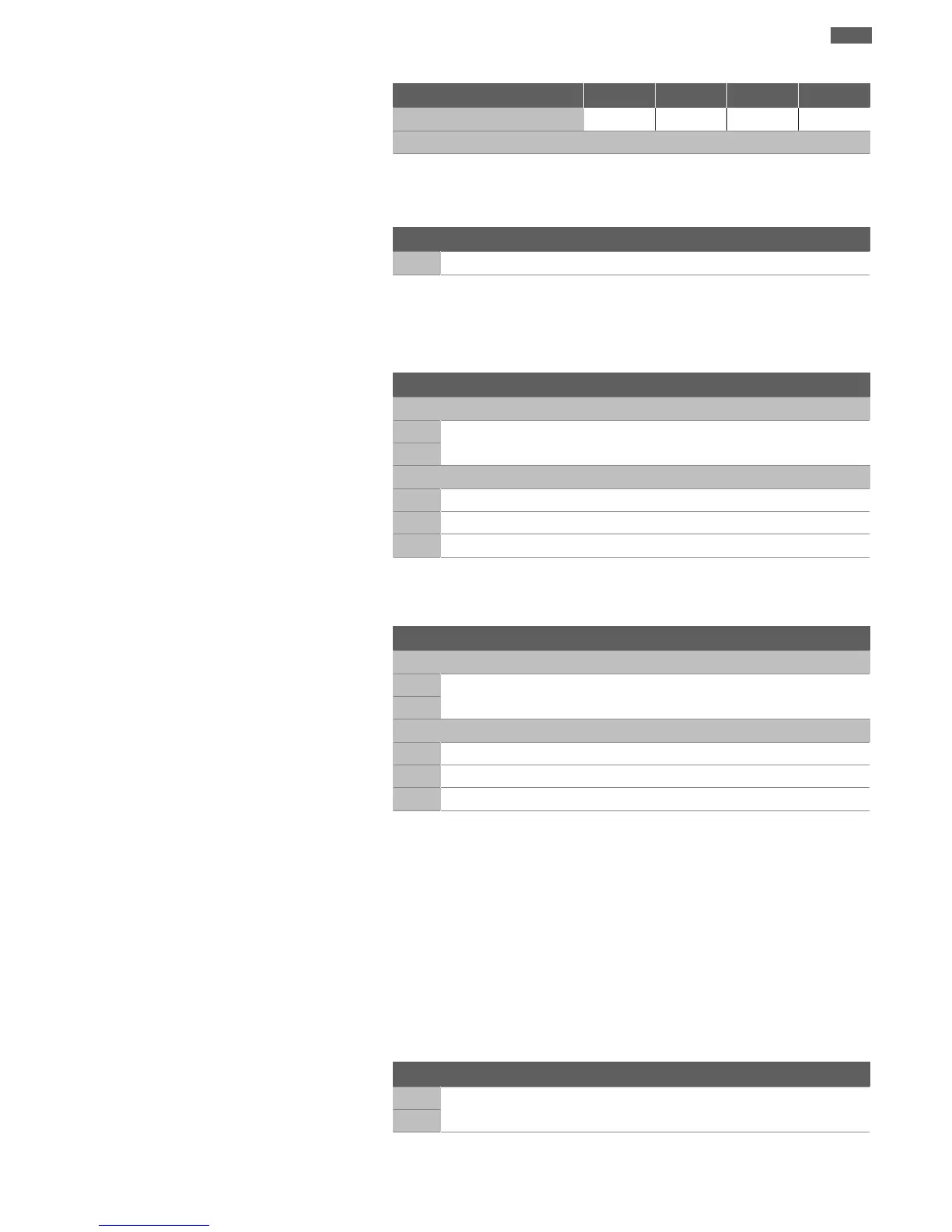
External electrode
o o - -
Key: - = not available/possible, o = optional, • = as standard
All the monitoring devices fitted must always be connected!
6.5.4.1 Motor compartment/sealing
chamber monitoring
Connect the electrodes via an evaluation relay. Relay “NIV101/A” is recommended for
this. The threshold is 30kOhm.
Wiring diagram
DK
Electrode connection
When the threshold is reached, deactivation must take place!
6.5.4.2 Monitoring of motor winding
With bimetallic strip
Connect the bimetallic strips in the switchgear itself or via an evaluation relay.
Connection values: max. 250V(AC), 2.5A, cos φ = 1
Wiring diagram for bimetallic strip
Temperature limiter
20
Bimetallic strip connection
21
Temperature control
21
High temperature connection
20
Centre terminal
22
Low temperature connection
With PTC sensor
Connect the PTC sensor via an evaluation relay. Relay “CM-MSS” is recommended for
this. The threshold is preset.
PTC sensor wiring diagram
Temperature limiter
10
PTC sensor connection
11
Temperature control
11
High temperature connection
10
Centre terminal
12
Low temperature connection
Triggering status with temperature control and limiting
Depending on the version of the thermal motor monitoring, the following triggering
status must occur when the threshold value is reached:
▪Temperature limiting (1temperature circuit):
When the threshold is reached, deactivation must take place.
▪Temperature control (2temperature circuits):
When the threshold for the low temperature is reached, the motor can deactivate with
automatic reactivation. When the threshold for the high temperature limit is reached,
the motor must deactivate with manual reactivation.
Note the additional information in the chapter on potentially explosive areas found
in the appendix!
6.5.4.3 Monitoring of motor bearing
Connect the Pt100 sensor via an evaluation relay. Relay “DGW2.01G” is recommended
for this. The threshold is 100°C.
Wiring diagram
T1
Pt100 sensor connection
T2
When the threshold is reached, deactivation must take place!
 Loading...