Product description en
Installation and operating instructions Wilo-EMU FA + FK 17.1, FK 202, FK 34, FK 42 11
Inspection cover (depending on the hydraulics)
Additional opening on the hydraulics housing. This opening is used to remove clogging
in the hydraulics.
Casing and impeller wear rings (depending on the hydraulics)
The suction port and impeller are subjected to the most stress when pumping. In the
case of channel impellers, the gap between the impeller and the suction port is an im-
portant factor for a constant delivery rate. The larger the gap between the impeller and
the suction port, the higher the losses in the delivery rate and the risk of clogging in-
creases. In order to ensure long and efficient operation of the hydraulics, an impeller
wear ring and/or casing wear ring is installed depending on the impeller and the hy-
draulics.
▪Impeller wear ring
The impeller wear ring is attached to the channel impellers and protects the incoming
flow edge of the impeller.
▪Casing wear ring
The casing wear ring is installed in the suction port of the hydraulics and protects the
incoming flow edge in the centrifugal chamber.
The two components can be replaced easily when worn.
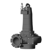
4.1.2 Motor
In the three-phase current version, self-cooling submersible motors are used as the
drive. The motor can be used in continuous duty both immersed and non-immersed.
Continuous duty is also possible in dry well installation. The roller bearings are perman-
ently lubricated, which means they are maintenance-free. The connection cable has
bare cable ends and the standard length is 10m. The cable length can be adapted ac-
cording to the order.
4.1.3 Cooling system
The motor has an active cooling system. For the cooling, the motor is filled with medi-
cinal white oil. The coolant is circulated by an impeller. The impeller is driven by the
motor shaft. The waste heat is transferred directly to the fluid via the cooling flange.
The cooling system itself is not pressurised.
4.1.4 Seal
The seal for the fluid and the motor compartment is made via two mechanical seals. The
two mechanical seals are arranged in two different ways:
▪Version “G”: two separate mechanical seals
▪Version “K”: two mechanical seals in a block seal cartridge made of stainless steel
The sealing chamber between the mechanical seals is filled with medicinal white oil and
accommodates any possible leakage of the mechanical seal on the fluid side.
4.1.5 Material
The following materials are used in the standard version:
▪Pump housing: EN-GJL-250
▪Impeller: EN-GJL-250
▪Motor housing: EN-GJL-250
▪Seal on the motor side: SiC/SiC
▪Seal on the fluid side: SiC/SiC
▪Seal, static: NBR
The precise details of the materials are shown in the respective configuration.
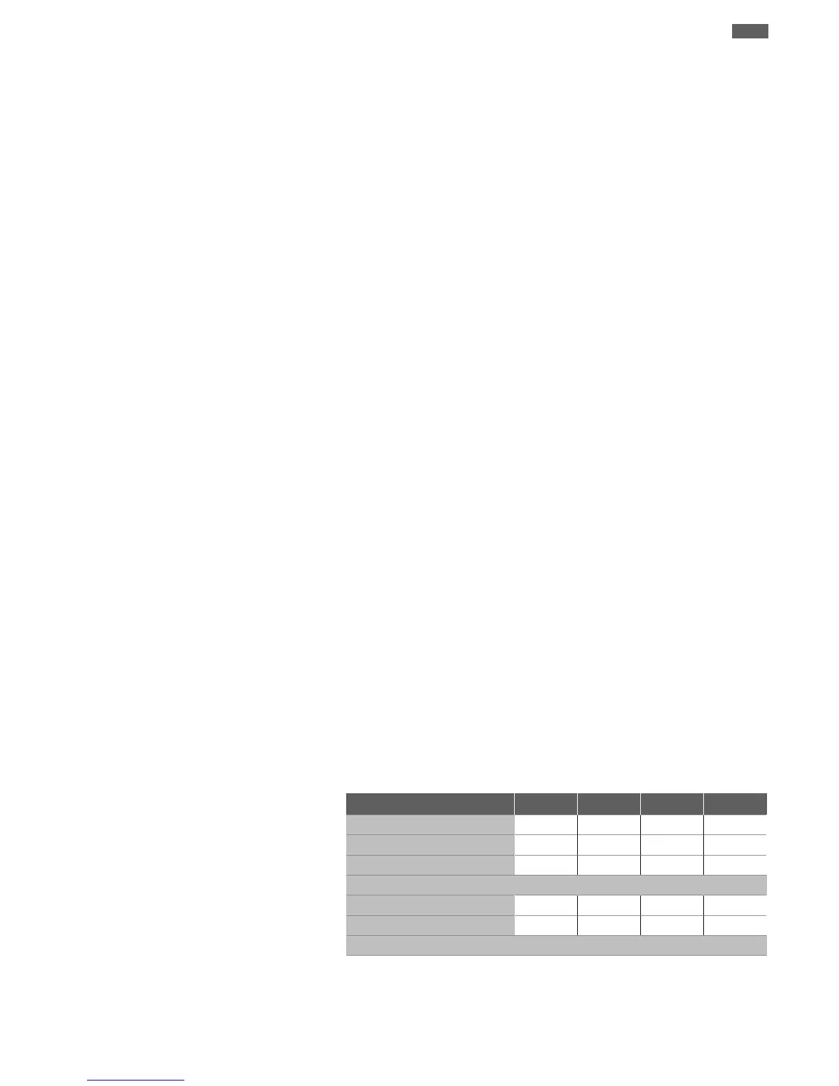
4.2 Monitoring devices
Overview of possible monitoring devices:
FK 17.1 FK 202 FK 34
FK 42
Motor compartment
- - • •
Motor winding
• • • •
Motor bearings
- - o o
Sealing chamber
Internal electrode
- - • •
External electrode
o o - -
Key: - = not available/possible, o = optional, • = as standard
All the monitoring devices fitted must always be connected!
Monitoring of motor compartment
The motor compartment monitoring protects the motor winding from short-circuits.
The moisture is measured by an electrode.
 Loading...