en Installation and electrical connection
24 WILO SE 2017-06
6.5.2.3 Testing the resistor of the ex-
ternal electrode for sealing cham-
ber control
Measure the resistor of the electrode with an ohmmeter. The measured value must ap-
proach “infinity”. For values ≤30kOhm, if there is water in the oil – change the oil!
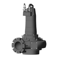
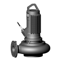
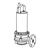
6.5.3 Three-phase motor connection
The three-phase current version is supplied with bare cable ends. Connection to the
mains is established by connecting the power supply cables in the switchgear. Refer to
the attached connection diagram for more precise details regarding the connection.
Electrical connection must always be carried out by a qualified electrician!
NOTICE!The individual wires are designated according to the connection diagram.
Do not cut the wires! There is no additional assignment between the wiring diagram
and connection diagram.
Wiring diagram of the power connections for direct activation
U
Mains connection
V
W
PE (green-yel-
low)
Earth
Wiring diagram of the power connections for star-delta starting
U1
Mains connection (start of winding)
V1
W1
U2
Mains connection (end of winding)
V2
W2
PE
Earth
6.5.4 Monitoring equipment connection
Refer to the enclosed connection diagram for details regarding the connection and in-
stallation of the monitoring devices. Electrical connection must always be carried out
by a qualified electrician!
NOTICE!The individual wires are designated according to the connection diagram.
Do not cut the wires! There is no additional assignment between the wiring diagram
and connection diagram.
DANGER
Risk of explosion due to incorrect connection!
If the monitoring devices are not connected correctly, there is a risk of fatal injury
due to explosion in potentially explosive areas! Connection must always be carried
out by a qualified electrician. If used in potentially explosive areas:
• Connect the thermal motor monitoring via an evaluation relay!
• Deactivation by the temperature limiter must be conducted with reactivation
lock! It must only be possible to restart the unit when the unlock key has been
actuated by hand!
• Connect the external electrode (e.g. sealing chamber control) via an evaluation
relay with an intrinsically safe circuit!
• Note the additional information in the chapter on potentially explosive areas
found in the appendix of these installation and operating instructions!
Overview of possible monitoring devices:
FK 17.1 FK 202 FK 34
FK 42
Motor compartment
- - • •
Motor winding
• • • •
Motor bearings
- - o o
Sealing chamber
Internal electrode
- - • •
 Loading...