English
20 WILO SE 12/2008
Key to figures:
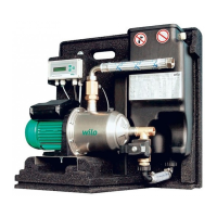
Fig. 1 Overview of Wilo-RainSystem AF Comfort
1 Centrifugal pump
2 Base frame
3Switchgear
4 Potable water replenishment reservoir
5 Connection for potable water supply
6 Pressure port connection
7Pressure sensor
8 Suction port connection
9 Solenoid valve
10 Connecting piece for the replenishment reservoir
11 Overflow funnel
12 Level sensor
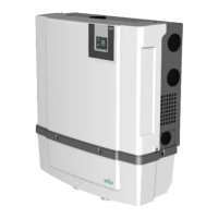
Fig. 2 Overview of switchgear
1 Display
2 Status indicator
3 “Go back” button
4 “Go forward” button
5 Confirmation (OK) button
6 Internal connections
7 Connection for pressure sensor
8 Connection for level sensor
9 Optional connection for reed relay
10 Enclosure screws
Fig. 3 Example installation with Wilo-RainSystem AF
Comfort
1 Collector tank
2Level sensor
3 Suction line with foot valve
4 Filter collector
5 Wilo-RainSystem AF Comfort
6 Potable water connection
7 RainControl Economy (RCE) switchgear
8 Solenoid valve
9Pressure sensor
10 Centrifugal pump
11 Overflow funnel
12 Pressure pipe supplying consumers
13 Auxiliary earth terminal
Fig. 4 Assignment of levels to the switchgear menus
Fig. 5 Level sensor connection
Fig. 6 Hydraulic connection diagram/dimension
drawing
1Cover
2 Compartment for Installation and operating
instructions
3Overflow
4 Mains connection (cable length approx. 2.5 m)
5 Level sensor (cable length approx. 20 m)
(within the scope of delivery! Installation
by customer/processor)
6 Auxiliary earthing screw
7G1" Suction connection for rainwater storage
8Rp 1"; Pressure port
9R¾"; Potable water connection
10 Overflow funnel with HT70 connection (DN75)
Fig. 7 Filling centrifugal pump and suction line
Fig. 8 Drilling diagram for wall mounting
Free space needed for maintenance work
Fig. 9 Electrical connection diagram
 Loading...