English
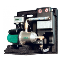
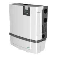
Installation and operating instructions RainSystem AF Comfort 35
2.07 h overflow • Password 01 is required
Setting of the height (H) of the overflow above the tank floor
(absolute value)
000 – H
max
[cm]
H > height of sen-
sor (menu 2.06)
H < tank height
(menu 2.05)
000 cm
> 000 cm <
2.09 top up lev. • After-sales service password is required
Setting of the level (H) at which the unit switches over to
potable water replenishment, based on the height at which
the level sensor is fitted above the tank floor (menu 2.06)
000 – H
max
[cm] 005 cm
> 005 cm <
2.10 top up qua. • After-sales service password is required
Setting of the top-up level for potable water replenishment/
hysteresis, measured in relation to the level of the potable
water replenishment reservoir (menu 2.09)
03 – 19 cm 03 cm
>03cm <
2.12 pump on at • After-sales service password is required
Setting of the set pressure for pump switch-on
1.0 – 4.5 bar 1.2 bar
>1.2bar <
2.13 pump off at • After-sales service password is required
Setting of the set pressure for pump switch-off in rainwater
operation; dependent on the setting for switch-off logic
(menu 2.50), the jumper configuration and the set pressure
for pump switch-on (menu 2.12)
1.5 – 9.0 bar,
min. 0.5 bar >
pump switch-on
set pressure
(menu 2.12)
3.9 bar for MC 304
or
4.9 bar for MC 305
> 3.90 bar <
2.14 pump overrun. • After-sales service password is required
Run-on time of the pump
00 – 59 sec 20 sec
>20sec <
2.15 dry-run.del • After-sales service password is required
Time delay until a dry-running fault signal is triggered. Fault
will be displayed if a minimum pressure of 1 bar is not reached
within the set time.
05 – 59 sec 30 sec
>30 sec <
2.16 furring Pro • After-sales service password is required
Setting of the time interval for brief opening of the valve to
prevent lime deposits
0 – 7 days
0 = inactive
7 days
>7 day(s) <
2.17 action E4 • Password 01 is required
To configure an optional sensor connected to input 4 as a
normally open contact (“closes”) or normally closed contact
(“opens”).
(For assignment of sensor, see menu 2.24)
opens
closes
closes
>closes <
2.19 flush out • After-sales service password is required
Setting of the period of time after which the unit switches
automatically to potable water mode for cleaning
(for duration of cleaning, see menu 2.20)
01 –28 days 21 days
> 21 days <
2.20 flush time • After-sales service password is required
Setting of the length of time for which the unit is to operate
automatically in potable water mode for cleaning. The pump
running time is the crucial factor here.
(For the cleaning interval, see also menu 2.19).
01 – 59 min 03 min
>03 min <
2.21 max. time p • Password 01 is required
Setting of the maximum permissible continuous running time
for the pump
000 – 360 min
000 = deactivated
000 min.
> 000 min <
2.24 connect E4 • Password 01 is required
Selection of sensor assignment on input 4. Discrimination is
by means of an external resistor.
(For the action of the sensor, see menu 2.17)
back pressure
overflow
back pr.+overflow
back pressure
> back pressure <
2.25 alarm level Display of the alarm level for high-water level (flooding).
The following formula applies: overflow height (menu 2.07)
+ 25 cm.
Menu 2.07+/-
100 cm
2.07 +25 cm
(Display of infor-
mation only)
> 2.07 + 025 cm <
Menu Description Parameters Factory settings
 Loading...