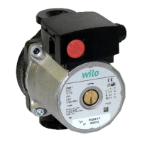
Installation and Operating Instructions Wilo-Yonos PARA 19
English
7 Installation and electrical connection
DANGER! Danger of death!
Incorrect installation and electrical connection can result in fatal injury.
• Installation and electrical connection may only be carried out by qualified
personnel and in accordance with the applicable regulations!
• Adhere to regulations for accident prevention!
7.1 Installation
• Only install the pump after all welding and soldering work has been completed
and, if necessary, the pipe system has been flushed through.
• Install the pump in a readily accessible place for easy inspection and dismantling.
• When installing in the feed of open systems, the safety supply must branch off
upstream of the pump (DIN EN 12828).
• Install check valves upstream and downstream of the pump to facilitate a possible
pump replacement.
• Perform installation so that any leaking water cannot drip onto the control
module,
• To do this, aline the upper gate valve laterally.
• In thermal insulation work, make sure that the pump motor and the module are
not insulated. The condensate-drain openings must remain uncovered.
• Install the pump with the power switched off and the pump motor in a horizontal
position see fig. 4 for installation positions of the pump.
• Direction arrows on the pump housing indicate the direction of the flow.
7.2 Electrical connection
DANGER! Danger of death!
A fatal shock may occur if the electrical connection is not made correctly.
• Only allow the electrical connection to be made by an electrician approved
by the local electricity supplier and in accordance with the local regulations
in force.
• Disconnect the power supply before any work.
• The current type and voltage must correspond to the details on the name plate.
• Maximum back-up fuse: 10 A, slow bow.
• Earth the pump according to the regulations.
• Mains connection: L, N, PE
• Connect the power cable:
1. Standard: 3-core overmoulded cable solution with brass end splices
2. Optional: Molex 3 way plug Fig.6
3. Optional: Wilo-Connector (Fig. 5a to 5e).
Dismantle the Wilo-Connector in accordance with fig. 5f, a screwdriver is
required for this.
• Connect the signal cable (PWM) as following:
• Brown, PWM + (signal characteristics)
• Blue, PWM – (ground)
om_yonos_para_oem__4523676_01__1205_de_en_fr.book Page 19 Tuesday, May 22, 2012 1:49 PM

 Loading...