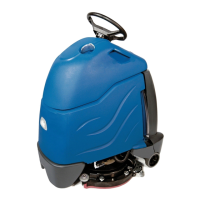
VAC
MOTOR
1.
Remove hose from exhaust horn on
motor.
2.
Remove
(2)
screws holding vac ex
-
haust deflector. set aside.
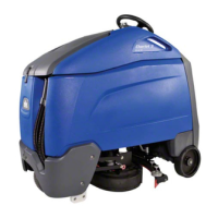
3.
Tilt machine back on handle. Remove
(2)
bolts holding vac motor mounting
bracket
to
base. Return machine to
upright position. Disconnect wire
leads
ar?d remove vac motor.
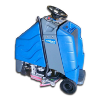
4.
To inspect motor brushes, remove
brush holder assembly. Brushes
should be replaced when worn to
318
inch or after about
750
operating
hours. After second brush replace
-
ment, the armature commutator
should be checked for pitting and
concentricity.
Vac motors can be re
-
paired but such repairs should be
made by a qualified motor repair shop.
.
-
"
-
-
-
A
PUMP ASSEMBLY
1.
Disconnect pump motor leads. Re
-
move (4) screws holding pump to
chassis. Disconnect solution hoses
from pump head and lift out pump.
Refer to pump drawing for replace
-
ment parts.
CAUTION:
When replacin
hose
-
barbs
on pump head
-
DO NO?
OVER
-
TIGHTEN
-
as this could crack intake
and exhaust ports in pump head.
WARNING:
The internal solution
hoses are encased
in
an outer hose
to
protect the electrical component parts
in the unlikely event a solution hose
should rupture. Replace hoses exactly
as
originally supplied.
SOLENOID & SOLUTION VALVES
1. Remove recovery and solution tanks.
2.
Remove auxiliary solution Outlet
nipple.
3.
Remove solution valve lever.
4.
Remove
(2)
screws holding valve
clamp chassis.
5.
Lift out valve asm. and disconnect
solution hoses. Repair as required.
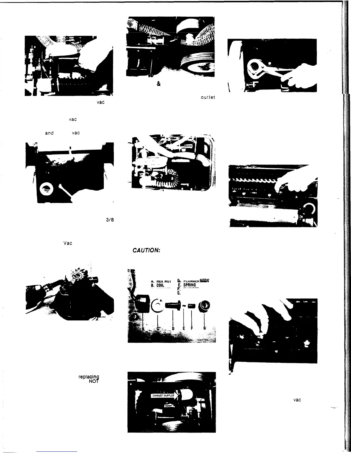
NOTE:
The solenoid valve can be dis
-
assembled for cleaning when positive
shut
-
off is interrupted and valve leaks
through tee jets.
6.
Remove hex nut at top of valve and
lift off coil assembly.
7.
Use spanner wrench or small punch
and hammer to remove plunger body.
Remove lint and soap residue from
p
I
u
n g e r
.
CAUTION:
When re
-
installing valve
make sure arrow is pointed in the di
-
rection of solution flow.
sff.
A.
HEX
NUT
C.
WASHER
F.
PLUNGER
0.
PLUNGER
BODY
0.
VALVE
BODY
2.
Tilt machine back on handle. Remove
exhaust deflector and Hex retaining
nut from PVC muffler. Repair or
replace as required.
MAN
I
FOLD ASSEMBLY
1.
Remove pump from chassis
to
access
solution outlet hose.
2.
Remove hose from hosebarb.
3.
Tilt machine back on handle. Remove
(2)
screws holding manifold
to
chassis.
Remove manifold and repair as re
-
required.
SPRAY JETS
To prevent clogged jets due to alkaline
build
-
up, the spray system should be
flushed with 1 or
2
gallons
of
clean hot
water at the end of each day. The machine
is
equipped with
"
quick change
"
jets
that can be easily removed for cleaning.
To remove
-
push jet in and rotate 1/4
turn. Wash jets and blow dry.
Do
not
use pins or wire
to
remove obstruction
as this will change spray pattern.
VAC EXHAUST MUFFLER
1. Remove exhaust hose from muffler
elbow.
BRUSH
DRIVE MOTOR
1. Remove exhaust hose from vac motor.
2.
Disconnect motor lead wires.
3.
Move brush adjustment lever to
lowest
position and tilt machine back on
handle.
4.
Remove
(4)
motor retaining bolts.
4