EasyManua.ls Logo

Winegard RS-1500 User Manual

Winegard RS-1500
4 pages
To Next Page IconTo Next Page
Page #1 background imageLoading...
Page #1 background image
MODEL RS-1500
OMNIDIRECTIONAL TV/FM ANTENNA
PARTS LIST
WARNING!
To prevent FIRE or SHOCK HAZARD, avoid exposure of power
supply to moisture.
NOTE: Please read all instructions before beginning installation!
#1. ANTENNA
#3. CABLE TOOL
#8. CARRIAGE
BOLT
#6. NYLOCK HEX NUT
#2. COAX CABLE
TOOLS NEEDED
#2 Phillips screwdriver
7/16” wrench
Crimping tool
Medium slot screwdriver
Cable tool (provided)
Wire stripper
WINEGARD
®
1. (1) Antenna
2. (1) 15' RG-6 Low Loss Coax Cable
3. (1) Cable Tool
4. (1) Power Supply RV-7542
5. (1) 5’ Power Harness
6. (4) 1/4-20 Nylock Hex Nuts
7. (4) 1/4-20 Carriage Bolts
8. (2) Insulated Quick-Disconnect
Terminals
9. Mount
10. (4) Lag Screws 1/4” x 1/4”
11. (4) Washers 1/4”
12. (1) Roof Gasket
13. (1) Cable Gasket Plug
14. (1) Antenna Gasket
15. Stem Mount
#4. POWER SUPPLY
& screws (2)
#14. ANTENNA
GASKET
#11. WASHERS
#10. LAG SCREWS
#15. STEM MOUNT
#12. ROOF GASKET
#13. CABLE
GASKET PLUG
#8. INSULATED QUICK
DISCONNECT TERMINALS
#5. 5’ POWER HARNESS
Winegard Company • 3000 Kirkwood Street • Burlington, IA 52601 • 319/754-0600 Fax 754-0787 • www.winegard.com
Printed in U.S.A. © 2002 Winegard Company 2451233
Question and Answer IconNeed help?

Do you have a question about the Winegard RS-1500 and is the answer not in the manual?

Winegard RS-1500 Specifications

General IconGeneral
TypeOutdoor TV Antenna
Reception RangeUp to 70 miles
Weight12 lbs
Impedance75 ohms
Wind SurvivalUp to 100 mph
MountingMast
PolarizationHorizontal
Frequency RangeVHF 54-216 MHz, UHF 470-890 MHz

Summary

Before You Mount Antenna

Installing Antenna Mount

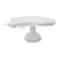
Instructions for mounting the antenna to a roof or wall using gaskets and plugs.

Connecting Coax Cable to the Antenna

Steps to connect the coaxial cable to the antenna using a cable tool.

Installing Antenna on Mount

Securing the antenna to the mount using bolts and nuts for stability.

Connecting Power Supply

Power Supply Wiring and Connections

Details on connecting the 5' wire harness, 12 VDC source, and other cables to the power supply.

Checking Operation of Power Supply

Power Supply Test Procedure

Procedure to verify power supply function by tuning TV and checking picture quality.

Troubleshooting Antenna Issues

System Operation Overview

Explanation of how the antenna system works, including power and signal flow.

System Testing and Voltage Checks

Steps to test the system and check for +12 VDC at specific test points.
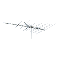
Related product manuals