Do you have a question about the Wireless-tag SigmaStar SSD201 and is the answer not in the manual?
| Brand | Wireless-tag |
|---|---|
| Model | SigmaStar SSD201 |
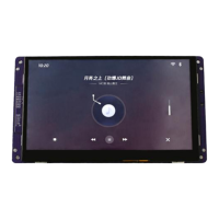
| Category | Monitor |
| Language | English |
Lists CPU, Video processor, RAM, Storage, OS, Ethernet, WIFI, Display, Audio, Serial port, USB, TF card, RTC, Extension interface specs.
Details power supply, voltage range, and rated power for the device.
Specifies operating and storage temperature ranges for the device.
Provides a visual layout of the motherboard and its various connectors and ports.
Describes the power input connector and pinout, plus RS232/RS485 serial interfaces.
Details the 50-pin FPC connector for RGB display output and its pin definitions.
Explains the CTP (Capacitive Touch Panel) and RTP (Resistive Touch Panel) interfaces.
Describes the dual-channel speaker output connector and pin definitions.
Outlines the digital microphone interface connector and its pin definitions.
Details the analog microphone interface connector and its pin definitions.
Specifies support for standard MicroSD cards and file systems.
Describes the 1-channel USB2.0 Type-A female connector.
Details the 1-channel 10/100Mbps adaptive Ethernet interface.
Mentions the IPEX antenna connector used on the board.
Explains the UART_PM interface for debugging via a 4-pin connector.
Describes the interface for connecting an external ESP32 module for Wi-Fi/BT/BLE.
Details the 6-pin PH2.0 connector for general purpose input/output.
