Pag. 5
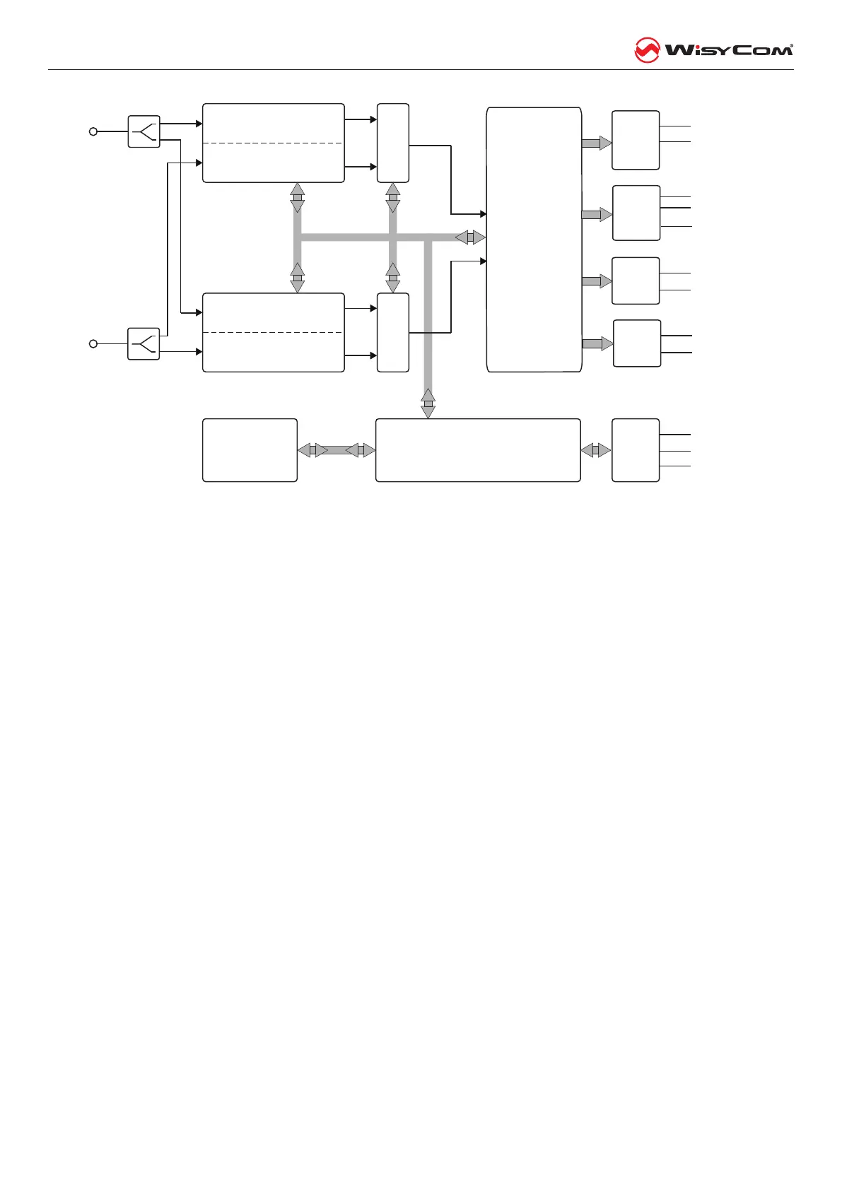
MRK960 dual true diversity receiver
MRK960: main block diagram
Receiver - 1- A
Receiver - 1- B
Receiver - 2- A
Receiver - 2- B
True Diversity
Control Rx 1
True Diversity
Control Rx 2
Communic.
and control
interface
Receiver supervisor
microcontroller
and user interface
Front panel
Digital
output
A
B
Antenna inputs
Line 1
Line 2
Com Rx 1
Com Rx 2
AES3 Output
INFRARED
USB
Digital
audio
processor
Analogue
output
PTT
output
Ear-ph Left
Ear-ph Right
Ear-
phone
work clock
Ethersound
Ethernet
The data sub carrier is digitally ltered to a very selecve equivalent lter (bandwidth 3Hz). Each lter has its
own data demodulator, one for medium speed data detecon at the output of the rst lter and one at low
speed data detecon at the output of the second lter. All the two demodulators are connected to the super-
visor micro controller for the data baery detecon and signalling.
Digital audio processor(for each receiver): the demodulated signal is ltered by an an aliasing low pass lter
and then converted in the digital domain with a 96KHz 24bit audio A/D converter. The digital signal processor
(DSP), working in double precision, replicates all the analog funcons with very high accuracy, ultra low distor-
on and without typical analog problems like components tolerances or long term or temperature dris etc.
The high speed audio algorithms maintains the audio delay at about 0.390 milliseconds, making it ideally for
live events and to keep audio delay as short as possible. The DSP unit also lters and demodulates the data
carrier and communicates all the parameters and informaons to the supervisor micro controller. The audio
output goes to the digital outputs (AES3) or is converted in the analog domain with a high quality 24 bits
96KHz D/A converter and an an-aliasing lter.
The analogue audio signal is routed in three parallel ways, LINE, COM and HEADPHONE MONITOR amplier.
The HEADPHONE MONITOR amplier is controlled by the buons on the front panel and by the volume knob.
The monitor output depends on the squelch and on the tone squelch only in the TSQ ON selecon. In TSQ OFF
and in TSQ ADV the monitor output is muted only by the squelch control.
The two analogue audio ways, LINE and COM, has the same audio quality and are controlledy by the “Tone
squelch matrix”. Each audio driver has a VCA for the so switching of the audio signal and the mung func-
ons, controlled by the supervisor microcontroller. Aer the VCA, an electronically balanced amplier drives
the output signal, directly or thru a very low impedance screened audio transformer (oponal). The audio
output without transformer could withstand up to +52 Vdc of phantom supply with no damage and up to
100V with transformer.