Pag. 7
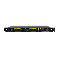
MRK960 dual true diversity receiver
RECEIVER 1 and RECEIVER 2
Area A: 3 LED bars:
• twobarsfortheRFlevelsindBuVolt(diversityA&Bantennalevel),
• FMmodulationofthereceivedchannel(modulationin%referredtothenominaldeviation)
• LIN:audioinlineoutputactive
• COM:audioincomoutputactive(optional)
• GPI:g.p.i.commandthruopto-isolatedrelay,active(optional)
• DATA:datasubcarrierfrommicrophonetransmitterdetected
Area B:display(256x64pixelsyellowOLEDdisplay)
Area C:3pushbuttons(membrane).
Thefunctionofeachbutton(upper,middleandlower)willbereadablefromthecontextmenuonthe
display.
Area D:Pushrotaryknobandlightindicator
Warning(YELLOW)andAlarm(RED)lightindicator:
• YellowFixed lightindicator(Warning)whenthereisnoaudioinboththeaudiooutputs(COMand
LINE)
• RedSlowBlinking lightindicator(LowAlarm)whenthebatterylevelofthetransmitteris≤25%
• RedFastBlinkinglightindicator(MediumAlarm)whenthebatterylevelofthetransmitteris≤12%
• RedFixedlightindicator (HighAlarm)whenabooster(AorB)hasashortcircuit.Moreoverthefol-
lowingmessageappearsontheOLEDdisplay:“OverCurrentonantennaA/B”
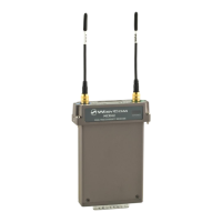
MONITOR
Monitor 1 and 2:it acvates monitor audio on jack output (6.3mm - ¼”) for receiver
1 and 2, respecvely (a green LED is lighted when audio is enable). Audio level can be
adjusted with the rotary knob. The red led (CLIP) indicates a clipping in the audio moni-
tor output.
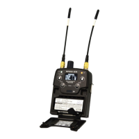
POWER & BOOSTER
BOOSTER:it acvates antenna powering (boosters) with 12VDC (200mA max) and the
green LED is lighted. Blinking LED indicates a faulty condion, in this case power down
the device and check for short circuits or overloads in the RF cables or boosters.
Booster supply for antenna A and antenna B are indipendent, switchable from the RA-
DIO > OPTIONS menu.
POWER: ON/OFF square powering buon turns on/o the receiver. When in OFF posi-
on both phases are disconnected from power.
A B C D