B
Bruce TaylorSep 10, 2025
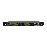
What to do if WisyCom MCR42 Receiver displays 'PLL unlocked'?
- SStephanie McdonaldSep 10, 2025
If your WisyCom Receiver displays 'PLL unlocked', it indicates an error during frequency tuning. In this case send to repair at Wisycom Repair Centre.