QUICK START INSTRUCTION
1. Connect to the power outlet using the supplied power cable (see rear panel: connector 2)
2. Attach the antennas to the antenna out BNC connections (see rear panel: connectors 8 and 13)
3. Connect the audio sources to the relative audio input connectors (see rear rear panel: connectors 7
for digital audio sources, connectors 9÷12 for analog audio sources)
NOTE: the cascade configuration allows to use the same analog audio input for more transmitter
4. Power on the MTK982
5. Switch off the RF output:
6. Enter in the AUDIO menu and
a. configure the input parameter between digital and analog (according to the audio
source connected at point 3)
b. configure the AF level meter parameter as modulation
c. if digital audio source:
• leave audio gain left and right parameters to 0dB and adjust the audio level
with the mixer
• if need change the audio gain left and right parameters
d. if analog audio source:
• leave audio gain left and right parameters to 0dB and adjust Max audio level
parameter. NOTE: this parameters is unique for both the channels (right and
left)
• if need change the audio gain left and right parameters
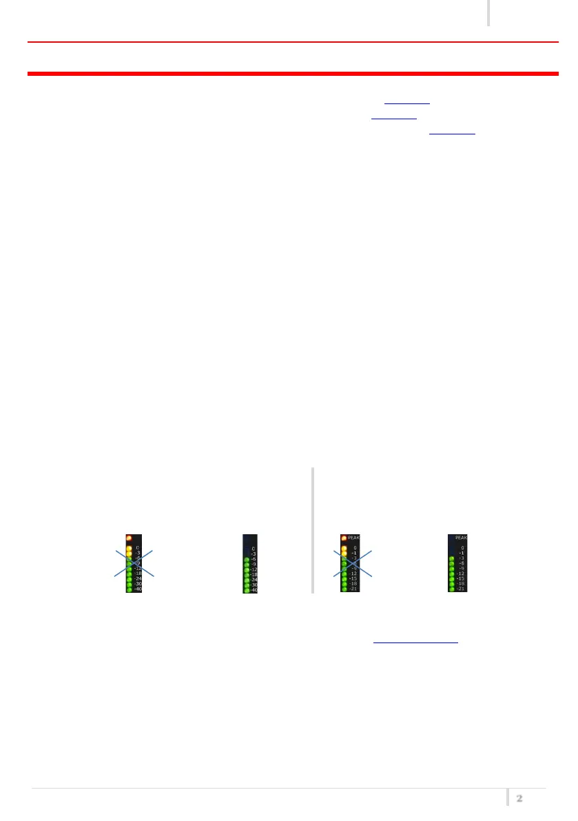
NOTE: adjust the audio level (thru the mixer and/or Max audio level and/or the audio gain left
and right parameters) so that, for the maximum input signal level,
the AF level bars show the MAXIMUM
NUMBERS OF GREEN LED INDICATORS AND NO
YELLOW/RED CLIP LED INDICATORS
the MOD. (modulation) bar shows the
MAXIMUM NUMBERS OF GREEN LED
INDICATORS AND NO YELLOW/RED PEAK
LED INDICATOR
7. Enter in the Ch-Gr menu and set the group/channel/ frequency
8. Enter in the PRESET menu and set the appropriate Preset (see Compatibility table for more detail)
9. Enter in the TX Power menu and set the TX power (10÷200mW)
10. Exit from the menu and switch on the RF power output pushing the ON/OFF button