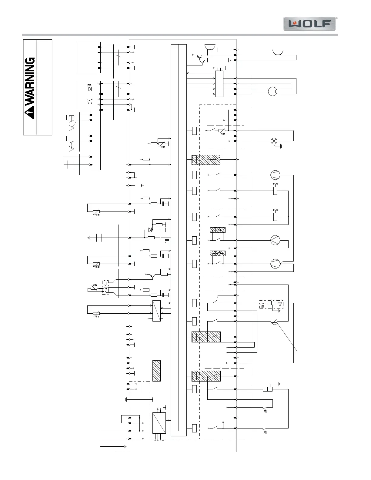
CSO24 and CSO30 (SWS #13508346)
Wiring Diagrams
7-2
#9001333 - Revision A - August, 2014
wh bubu vt b
u
rdbu wh oggy rd
r
d
bk bk rd
og
bkrd rd ye gy
ye ye
ye ye wh
bn bupkbu bk bu bn bn rd
bkbkbk b
k
bk pk ye rdbk
brblbl
bk
N' N
'
N'
L1
L1
L1
N
L2
L1
N'
L1
U5+
U12+
L1
N'
L1
N'
L1L1
N'
N
L1
N
'
L1
L1N
N'
U5+
L2
U5+ U5+
U5
+
U5+ U5
+
U5+
U1
2
+
U5+
U5+
U
5+
U1
2
+
U
5+
U5+ U12
+
N L2L1
K2
.
88
3
0
R
C-
Gl
ie
de
r
nicht best.
NC
NC
NC
NC
B
oi
l
er
on
D
rain pump
on
Coo
la
ir
fa
n
o
n
H
ot
a
ir f
a
n
on
I
n
l
et valve
on
Voltage generation
a
n
dco
n
t
ro
l
L
i
g
ht
i
n
g
o
n
Ma
in
rel
a
y
on
B
ott
o
m
h
ea
t
on
K3.1960
H
ot ai
r
on
K3.
5
87
6
F
l
a
p
on
K2
.94
0
6
K
3
.
19
1
7
NC
K3
.
1
9
09
Color code
b
ublue
bn brown
ye
yel
l
ow
gn green
gy grey
pk pink
rd red
og orange
vt violet
b
kb
la
c
k
wh whi
t
e
P59.078
Temperature
cl
i
mate
P59.106
NC
K3.
8
66
6
17
A
2
Cont
rol
uni
tK
3.2650
Cont
rol un
it K
3.
2650x
A3
LCD
-M
odul
K
3.8100x
8
Flansch
K2.3749
AD
Te
m
pe
r
atu
r
e
on p
ro
ce
ss
or
P59.040P59.081
Temp.
f
oo
d
probe
Presence
f
o
o
d
probe
1097.35R @ 25°C
P
5
9.
0
7
9
C
on
n
e
ct
i
on v
a
ria
n
t
sw
ith 3-
co
re ca
b
le
(W3 set on X1-5)
Power and resistance definitions
aredoneat240V~/25°C
K3
.8
6
55
K8.2160
W3 for
switchi
n
g
between
1-p
h
as
ea
nd
2-phase
connection
not assembled
K3.1905
K3
.
8
6
53
K3.1984
Load
max.
3A
Load
max.
3A
Load
ma
x.
3
A
Load
m
ax
.
16A
Lo
a
d
m
ax.
10A
L
oad
max.
10A
L
oad
max.
12A
Lo
ad
max
.
10A
Load
m
ax.
6A
Load
max.
3
A
Load
m
ax.
3A
Load
m
a
x.
3
A
Load
ma
x.
3
A
Mo
to
r
exhaust air slider
Lig
h
tin
g
cooking space
Op
t
io
n
a
l
beeper
Heater
h
o
tair
Heater
bottom
F
a
n
hot air
Fa
n
cool air
B
oi
le
r
inlet valve
B
o
ile
r
drain pump
H
e
ater
boile
r
Because of the high inrush current (up to 5A)
the PTC bottom heater must only be switched
on
i
ftheh
e
ater of the boil
er is
s
witc
h
e
do
ff.
K3.8668
K2.
8
454 K3.1974
K3.6
1
90
Temper
a
ture
coo
ki
ng
sp
ace
Mot
o
r
c
ontro
l
A/D
K8
.
2
1
61
Pr
o
gra
m
i
n
ginte
r
face
Temperature
w
a
te
r
boiler
Resistance
level pin
boiler
Re
p
l
a
c
eme
n
tb
u
l
b
Halogen G9
P65.304
K2
.94
0
5
K3.1728
W
a
ter l
e
akage
detection
K0.0489
K3.5488
A1
Pro
c
essor
K
3.2848
4kV
A/
DA
/
D A/DA/DA/
D
A/D
A/D A/D
S
o
le
n
o
id
flap
wa
ter
t
ank
o
pen
door
close
Pr
esenc
e
water tank
Door
control
missing
tank
present
P59.106
K3.5875
K2.4359
K2.
9
54
8
K
3.1
9
0
5
K3.4053
Socket
P
59.068
L1
N
L2
L1
PE
PE
2
40
V2
~
240V~
6
0H
z
60Hz
X
10-4
X
10-4
K12-2K12-2
X50X50
K1-2K1-2
X10-5X10-5
X29-1X29-1
E1
3
36W
E1
3
36W
X4-2X4-2
K
2-1
K
2-1
X
25
-
1
X
25
-
1
X4-1X4-1
X4-7X4-7
X4-5X4-5
77
K11-2K11-2
X3-1X3-1
K8
-1
K8
-1
X6-2X6-2
X19-4X19-4
X12-3X12-3
11
B3
NTC 100k
B3
NTC 100k
X11-1X11-1
X28-2X28-2
K14
-
1K14
-
1
N
S
S5
R
e
ed
N
S
S5
R
e
ed
X7-3X7-3
F1
250°C
F1
250°C
X26-4X26-4
X21-1X21-1
X3-3X3-3
X3-6X3-6
88
K3-2K3-2 K4-2K4-2
X3-8X3-8
X3-11X3-11
H4H4
Y
2
Y
2
X4-6X4-6
X10-3X10-3
X15-9X15-9
X10-7X10-7
X9-3X9-3
X1-5X1-5
F2
250°C
F2
250°C
X5-4X5-4
X19-2X19-2
K5-2K5-2
X7-1X7-1
M
M1
Ste
pp
e
r
M
M1
Ste
pp
e
r
3
4
6
1
X51X51
X9-2X9-2
X26-1X26-1
X3-5X3-5
X2-1X2-1
K2-2K2-2
K13-2K13-2
X8-2X8-2
X15-10X15-10
X10-1X10-1
K6-1K6-1
B2
N
TC 50
k
B2
N
TC 50
k
PE BA
X14-2X14-2
K9-2K9-2
X2-3X2-3
X
2
4
-
1X
2
4
-
1
K3
-
1K3
-
1
X19-3X19-3
X18-1X18-1
E1
0
3
5W
E1
0
3
5W
44
E11
10
W
E11
10
W
X14-1X14-1
X5-1X5-1
X15-1X15-1
K4-
1
K4-
1
X
8-1
X
8-1
99
E2
PTC 140W
E2
PTC 140W
K13
-
1K13
-
1
99
X2-5X2-5
X10-6X10-6
X10-2X10-2
1
0
1
0
X18-3X18-3
X93X93
Y
1
Y
1
X3-7X3-7
E8
max
.
27
W
E8
max
.
27
W
X12-4X12-4
K6-2K6-2
X3-9X3-9
X2-6X2-6
X4-4X4-4
X5-2X5-2
K1
0-
1K1
0-
1
X14-20X14-20
Rx
B6
Rx
B6
X21-3X21-3
X6-1X6-1
X18-2X18-2
K8-2K8-2
X1-3X1-3
K12
-
1K12
-
1
X
6-3
X
6-3
X29-2X29-2
22
X2-4X2-4
E6
1.5
kW
E6
1.5
kW
X26-2X26-2
K5
-1
K5
-1
B1
Pt
1
'0
00
B1
Pt
1
'0
00
E4
2.07kW
E4
2.07kW
X9-1X9-1
X14-3X14-3
X5-3X5-3
K10-2K10-2
X3-10X3-10
X11-2X11-2
X6-2X6-2
X3-4X3-4
B5
NTC
2
30k
B5
NTC
2
30k
X14-4X14-4
S4S4
X21-2X21-2
X15-2X15-2
K9
-
1K9
-
1
2
0
2
0
X12-2X12-2
X26-3X26-3
Rx
B4
Rx
B4
X12-1X12-1
K1-1K1-1
K1
1-
1K1
1-
1
X18-7X18-7
X1-1X1-1
X3-2X3-2
X4-3X4-3
X2-2X2-2
X28-1X28-1
K14
-
2K14
-
2
X19-1X19-1
-This wiring information is provided for use by qualified service personnel only.
-Disconnect appliance from electrical supply before beginning service.
-Be sure all grounding devices are connected when service is complete.
-Failure to observe the above warnings may result in severe electrical shock.
 Loading...