Do you have a question about the Wolf Wall Ovens and is the answer not in the manual?
Overview of the Wolf Wall Oven Technical Service Manual and its purpose.
Details on product safety labels, signal words (WARNING, CAUTION), and precautions.
Contact information and office hours for Wolf Appliance Company support.
Summary of 2 & 5 Year Warranty, details, and notes.
Key to understanding the components of Wolf wall oven model numbers.
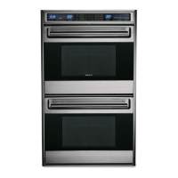
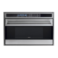
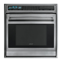
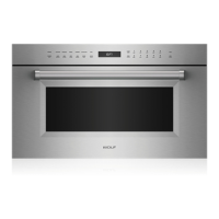
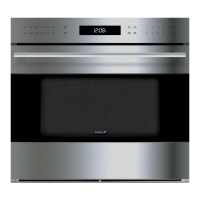
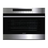
Illustrations and descriptions of 30" and 36" single oven models.
List of features and functionalities available in Wolf Wall Ovens.
Specifications for electrical supply and minimum wire size for oven installation.
Steps and precautions for physically installing the oven and attaching trim kits.
Overall dimensions for 30" single, 36" single, and 30" double ovens.
Diagrams for undercounter and front cutout dimensions for 30" single ovens.
Diagrams for undercounter and front cutout dimensions for 36" single ovens.
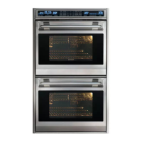
Diagrams for front cutout and side view for 30" double ovens.
Diagrams for undercounter cutout dimensions for side-by-side installations.
Definitions of key terms and descriptions of electronic control system components.
Instructions for Field Option Mode, User Preference Offset, and Temperature Display Preference.
Using the temperature probe to monitor internal food temperatures.
Steps for initiating and exiting the self-cleaning cycle.
How to engage panel lock, set the clock, and overview of diagnostic mode.
List of error codes and procedures for testing system components.
Procedures for removing the control panel and its associated drive motor.
Accessing and removing latch cover, door latch assembly, and limit switch.
Steps to remove the oven control board, stepper motor control board, and relay board.
Removing rack guides, oven lights, and convection baffle plate.
Removing convection fan, broil element, broil pan, and smoke catalyst.
Instructions for removing oven doors, adjusting them, and removing door gaskets.
Accessing and removing back panel, divider channels, cooling fan, and bake element.
Removing channel venting, hinge pocket, enclosure, and insulation.
Procedure for removing the fan apparency switch.
Guidance on navigating the troubleshooting section and identifying problems.
Steps to enter diagnostic mode for various oven configurations.
Table listing error codes, possible causes, and recommended tests/actions.
Procedures for testing elements and Ohm testing elements at the relay board.
Procedures for testing fans, motors, RTD sensors, and probes.
Flow chart for troubleshooting oven controller communication and voltage issues.
Flow chart for diagnosing issues with the head assembly rotation.
Table of component part numbers, voltage, amperage, watts, and ohms.
Details on element/fan operation times and cooling fan activation temperatures.
Wiring diagram for Wolf 30" double wall ovens.
Schematic diagram for Wolf 30" single wall ovens.
Wiring diagram for Wolf 36" single wall ovens.
Schematic diagram for Wolf 36" single wall ovens.