Troubleshooting Guide
WWaallll OOvveennss
5-9
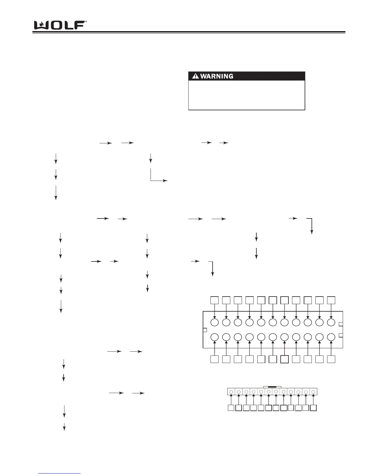
Troubleshooting Flow Chart
Step 4. Testing Oven Controller
Using a volt/ohm meter set to read DC voltage, at J2
Connector of the stepper motor control board, place
one meter probe to pin 1 and one meter probe to pin 2.
With harness connected and unit
turned "OFF", do you have
1 to 3 VDC at J2 from pin 1 to pin 2?
Yes
No
Replace oven controller.
Step 3. Testing Communications
NOTE: Following checks are performed with cables connected unless otherwise noted.
Do you have 36 to 41 VDC
at J11A (See Figure 2) from
Pin 1 to pin 2?
Yes
No
Do you have 36 to 41 VDC
Pins 14 & 17 at J4 or J5
(Controller)? (See Figure 1)
Step 2. Testing Voltage to Relay Board (Power reconnected to unit)
Check for voltage at E1 (L1)
to E2 (N) on relay board.
Do you have 120 VAC ± 10%?
Yes
No
Check for voltage at L1 and N
on terminal Block.
Do you have 120 VAC ± 10%?
Yes
Unit has loose or defective wire(s) between L1 of
terminal block and E1(L1) on relay board or N of
terminal block and E2 (N) on relay board.
Repair/Replace wires.
Go to step 3
No
Check for loose or defective wiring to unit
from terminal block to junction box/power
cord. May have to call an electrician.
Step 1. Check Wire Connections (Disconnect power to unit)
Check wire connections J4 and J5 on oven controller to J1
connector of relay board. Unplug both ends and reseat.
Check flex ribbon cable at J11A connector on oven controller,
unplug at oven controller and reseat.
Check wire connections at E1 (L1) and E2 (N) connector on
relay board, unplug both ends and reseat.
Replace Control Head Assy.
Do you have 8 to 11 VAC
from pins 8 & 9 at J11A
(See Figure 2) ?
Yes
With harness disconnected and unit
turned "OFF", do you have
4 to 6 VDC between pin 1 & pin 2
of harness?
No
Replace oven controller.
Replace Control Head assembly
Yes
Go to Step 4
DISCONNECT POWER TO UNIT BEFORE
UNPLUGGING WIRE(S) AND CONNECTIONS
WHEN PERFORMING CONTINUITY CHECKS,
POWER TO THE UNIT MUST BE DISCONNECTED
Yes
Do you have 36 to 41 VDC
Pins 14 &17 at J1
(Relay Board)? (See Figure 2)
Yes
Do you have 4 to 8 VAC between
pins 8 & 9 at J11A
(See Figure 2)
?
Yes
Replace Comm Cables
No
No
No
Replace Relay Board
No
Replace Control Head Assy.
Unplug ribbon cable, check for broken or bent pins.
If no broken or bent pins, reconnect ribbon cable.
2
64 8 10 12
16 18 20 22
1 3 5 7 9 11 13 15
17
19 21
1
2
12
11
3
4
5
67
8
9
10
Figure 1. J4 and J5 Configuration
Figure 2. J11a Configuration