Component Access and Removal
WWaallll OOvveennss
4-16
OVEN SIDE COMPONENTS:
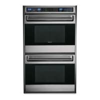
Channel Venting Removal
The channel is held in place by tabs at the rear and
screws at the front. To remove, extract the screws
around the channel. Now, lift the front of the channel
out slightly while disengaging the tabs on the channel
from the side enclosure. (See Figure 4-48).
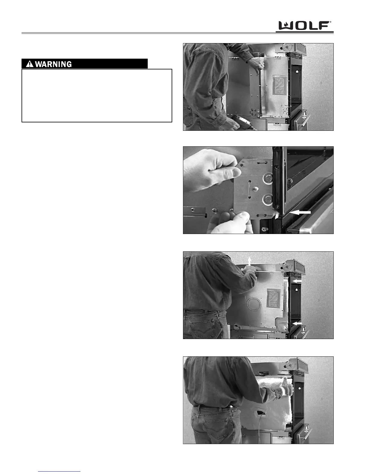
Hinge Pocket Removal
The oven door will need to be removed first. Now,
extract the screw from below the hinge slot at the front
bottom of the oven cavity. Extract the screws around
the hinge pocket and remove. (See Figure 4-49).
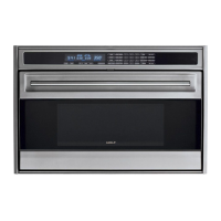
Enclosure Removal
First remove the channel venting and the hinge pocket.
Now, extract the screws from the hold down brackets
and remove. Then, extract the screws from around the
enclosure. Next, slide the enclosure towards the rear,
so that the front of the enclosure is out from behind the
oven cavity. Now, pull the top of the enclosure out from
under the pan module. Then, lift the enclosure from the
side of the unit. (See Figure 4-50).
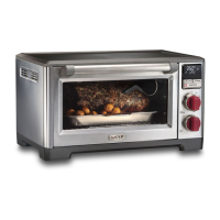
Insulation Removal
First, the channel venting, hinge pocket and enclosure
need to be removed. Now the hinge cavity insulation,
light insulation and cavity side insulation can be
removed. (See Figure 4-51).
IT IS NECESSARY TO REMOVE THE UNIT FROM
ITS INSTALLATION, REMEMBER THAT THE UNIT
COULD TIP FORWARD WHEN PULLED BEYOND
ITS INSTALLATION.
TO AVOID ELECTRIC SHOCK, POWER TO THE
UNIT MUST BE DISCONNECTED WHENEVER SER-
VICING AND/OR ACCESSING COMPONENTS.
Figure 4-48. Channel Venting Removal.
Figure 4-51. Insulation Removal.
Figure 4-49. Hinge Pocket Removal.
Figure 4-50. Enclosure Removal.