Do you have a question about the Woodward Peak 150 and is the answer not in the manual?
Essential safety measures to prevent static damage to electronic components during handling.
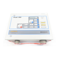
Details the enclosure dimensions and NEMA 4X requirements for the Peak 150 control.
Specifies vertical mounting requirements for the control enclosure on a wall or rack.
Covers wiring ports, routing, and shielding requirements for electrical connections.
Provides detailed instructions for preparing and installing shielded cable.
Overview of the microprocessor-based digital control for steam turbines.
Describes manual and automatic start modes for turbine operation.
Explains manual, remote speed set, and combination operating modes.
Lists the four methods of communication for the control.
Lists all inputs and outputs to the control enclosure.
Details power supply input connections and voltage/frequency specifications.
Describes the four relay outputs and their configurations.
Explains the eight discrete inputs and their functions.
Covers Modbus communication connections and requirements.
Details analog output connections and signal types.
Provides an overview of the control's system architecture and components.
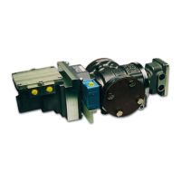
Details the function and connection of magnetic speed sensors.
Describes the analog input for remote speed set point.
Explains the governor speed control loop and set point adjustment.
Covers the control's diagnostic capabilities and features.
Details how to operate the control using the front panel interface.
Step-by-step procedure for starting the turbine.
Procedure for performing an overspeed test on the turbine.
Provides a summary of shutdown and alarm functions.
Instructions for using the hand-held programmer.
Details on configuring the control parameters.
Explains how to use the service mode for adjustments.
Defines the relationships between different speed points.
Overview of the alarms menu and its functions.
Adjusting gain and reset for speed dynamics.
Configuration for magnetic pickup failure override.
Procedure for checking input/output signals.
Settings for configuring speed parameters.
Configuration options for turbine start modes.
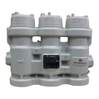
Settings related to the actuator configuration.
Details on configuring communication ports.
Explains the functional block diagram of the control system.
Details the wiring requirements for Modbus communication.
Provides a general overview of the Modbus protocol.
Lists and explains the Modbus addresses used by the control.
Information on the control's diagnostic features.
A chart to help diagnose common problems.
Details on alarm and shutdown conditions.
Addresses other potential operational issues.
Overview of available service options for the product.
Procedure for returning equipment for repair.
Information on how to contact Woodward for support.
| Category | Control Unit |
|---|---|
| Output Voltage | 5 VDC |
| Output Current | 3 A |
| Efficiency | 85% |
| Operating Temperature Range | -40°C to 85°C |
| Protection Features | Overvoltage, Overcurrent, Short Circuit |