EasyManua.ls Logo

Woodward VariStroke-I User Manual

Woodward VariStroke-I
133 pages
To Next Page IconTo Next Page
Page #1 background imageLoading...
Page #1 background image
Product Manual 26727
(Revision F, 8/2015)
Original Instructions
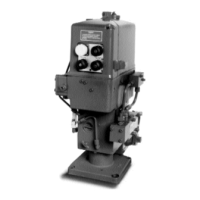
VariStroke-I (VS-I)
Electro-hydraulic Actuator
Installation and Operation Manual

Table of Contents

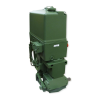
Other manuals for Woodward VariStroke-I

Questions and Answers:

Woodward VariStroke-I Specifications

General IconGeneral
BrandWoodward
ModelVariStroke-I
CategoryController
LanguageEnglish

Summary

General Information

Introduction

Detailed description of the VariStroke-I electro-hydraulic actuator and its capabilities.

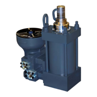
VS-I Integrated and Remote Construction

Overview of the major components and configurations of the VS-I actuator.

VariStroke Actuator Benefits

Key advantages including dirt tolerance, linearization, and side load capability.

Specifications

Physical and Performance Specifications

Details on bore/rod diameters, stall force, slew rates, accuracy, and failsafe operation.

Environmental Specifications

Operating limits for ambient temperature, vibration, shock, and corrosion resistance.

Electrical Specifications

Input/output signals, voltage, current, connections, and feedback device details.

Installation

Receiving and Unpacking Instructions

Procedures for handling and unpacking the VS-I actuator upon delivery.

Installation Instructions - General

Guidance on mounting, orientation, heat shields, and general setup considerations.

Hydraulic Connections

Details on supply, drain, and control port connections and tightening torques.

Service Tool Installation

Service Tool Setup and Connection

Requirements for PC service tool software, hardware, and port connections.

Connecting to the VariStroke-I

Step-by-step guide to establish communication between the service tool and the actuator.

Calibration and Monitoring

System Information Display

Overview of the service tool's system status and information pages.

Configuration and Calibration Page

Interface for setting operating parameters and initiating calibration procedures.

Find Minimum Stop Procedure

Process to set the actuator's minimum position and scale it to the demand range.

Configuration

Input Configuration

Settings for analog demand and feedback signals, including scaling and fault detection.

Output Configuration

Configuration options for discrete and analog outputs, including alarm and shutdown indications.

Advanced Configuration Parameters

Adjustments for bandwidth, dither, and silt buster functions for fine-tuning performance.

Repair and Troubleshooting

Troubleshooting Procedure

General guide for diagnosing and resolving system problems with the VS-I actuator.

Demand Fault Troubleshooting Guide

Specific troubleshooting steps for faults related to demand input signals.

Performance Fault Troubleshooting Guide

Guidance for diagnosing issues related to actuator performance and stability.

Product Support and Service Options

Product Support Options

Resources and contacts for installation assistance and unsatisfactory performance.

Returning Equipment for Repair

Instructions for packing and returning the VS-I unit for service.

Appendices Overview

Appendix A: V25 Servo, 4-inch Integrated Dimensions

Detailed outline drawings and installation features for the V25TD-10XX model.

Appendix C: V45 Servo, 6-inch Integrated Dimensions

Detailed outline drawings and installation features for the V45TD-15XX model.

Appendix G: V25 Servo, 4-inch Remote Dimensions

Outline drawings and installation details for the V25RD-10XX remote servo-cylinder.

Related product manuals