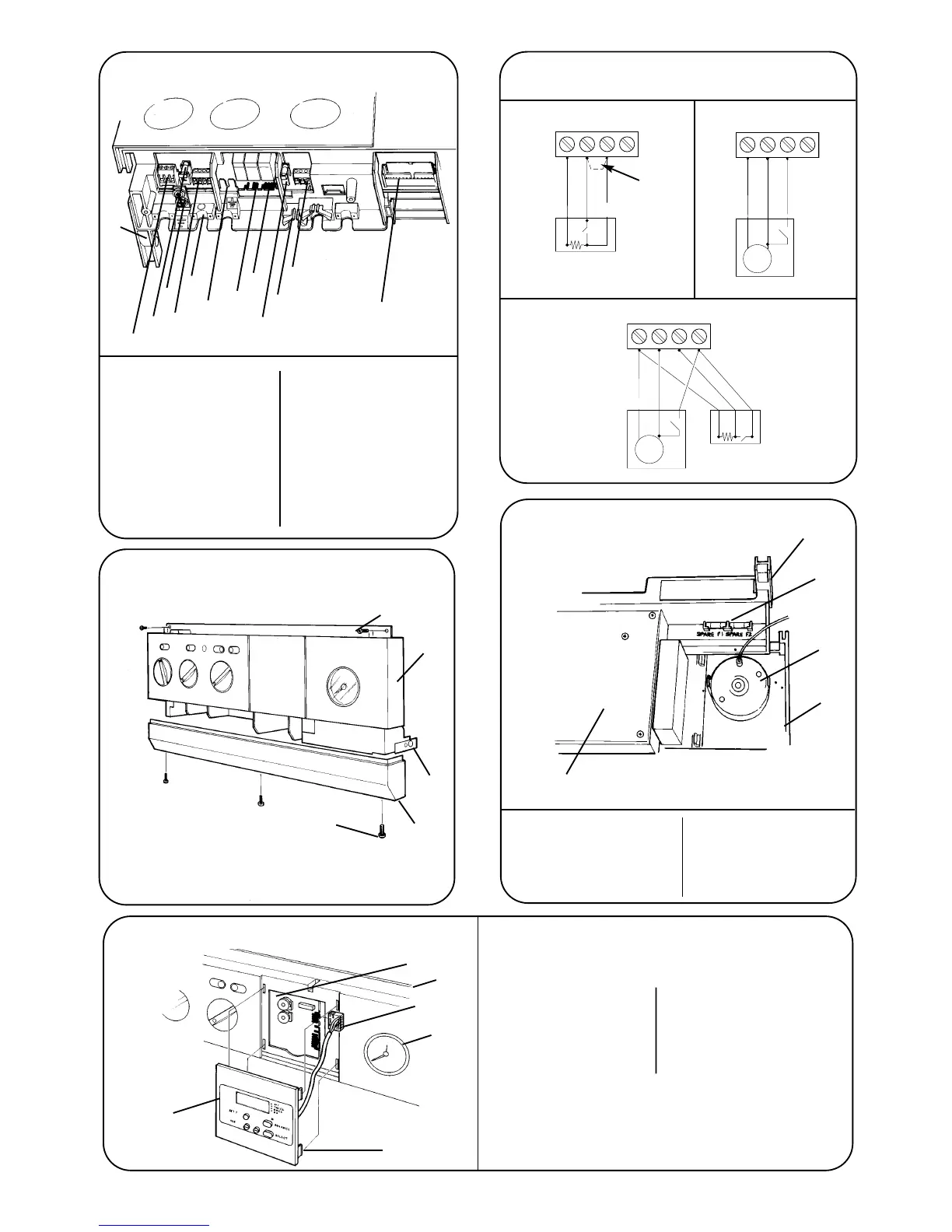
12
Fig 11 - Electrical Connections
13
1
2
3
4
5
6
7
8
9
10
11
12
1. ST12-Mains 9. Fuse-F2
2. Fuse-F1 10. Cable Entry Clamp
3. Earth Screw 11. ST13-24volt Controls
4. ST8-Room Thermostat 12. Main Harness and Clamp
and External Control 13. Control Panel Pivot
-Mains Voltage Point
5. Cable Entry Screw Clamp
6. Earth Tag
7. ST15-Pump
8. ST1-Fan
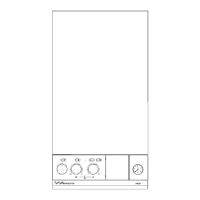
Fig 12 - Facia Connections Cover
1
2
3
4
5
1. Control Panel Fixing Screws
2. Facia
3. Control Panel Pivot Point
4. Connection Cover
5. Connection Cover Fixing
Screws
Fig 13 - Mains Voltage External Controls Connections
230 V Room Thermostat Connections
Ns
Ls
L
R
Spare
ST8
Ns
Ls
L
R
Spare
ST8
Remove Link
Neutral
Live
Switched Live
Neutral
Live
Switched Live
Motor
230 V Programmer Connections
230 V room thermostat and
Programmer Connections
Ns
Ls
L
R
Spare
ST8
Neutral
Live
Switched Live
Neutral
Live
Switched Live
Motor
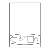
Fig 14 - Replacement Fuses
1
2
3
4
5
1. Control Panel Pivot 4. Facia Panel
Point 5. Control Board
2. Fuses-F1,F2 Assembly
3. Pressure Gauge
Fig 15 - Programmer Connection
6
5
4
3
1
2
1. Programmer
2. Programmer
Fixing Clip
3. Pressure
Gauge
4. Programmer
Connector
5. Facia
6. Control
Board
 Loading...