11.8 Air and Flue Duct Preparation
The method of installation of the flue system may be varied to
suit the actual site conditions. The instructions for connecting
and fixing the ducts must, however, be strictly followed.
Remove all packing material from the flue components.
The standard telescopic flue assembly is suitable for flues
from425mm (without cutting) up to 725mm measured from the
centre-line of the boiler flue outlet to the outer face of the wall.
Refer to Fig. 14.
If L is greater than 725mm then flue extension kits will be
required - each kit extends the flue by 750mm up to a maximum
of 2500mm. See table below.
EXTENSION MAXIMUM FLUE LENGTH mm
1 1475
2 2225
3 2500
11.9 Measure and Cut the Ducts
General: Cut the ducts as necessary, ensuring that the ducts are
square and free from burrs. Always check the dimensions before
cutting.
Measure the distance L. Refer to Fig. 16 and 17 .
The standard flue can be telescopically adjusted to any length
between 425mm and 725mm.
Fix the flue assembly together using the self-tapping screw
provided. Refer to Fig. 14.
It will only be necessary to cut the standard assembly if L is less
than 425mm. Cut the flue turret assembly and
the terminal
assembly by the same amount i.e L=350 - remove 75mm from
each
assembly.
Minimum side flue length = 335mm (accommodating a
10mm Service clearance and a 100mm wall)
Minimum rear flue length = 322mm (accommodating a
100mm wall)
If L is between 1175 - 1475mm (1 extension)
1925 - 2225mm (2 extension)
it is not necessary to cut the ducts.
12
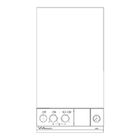
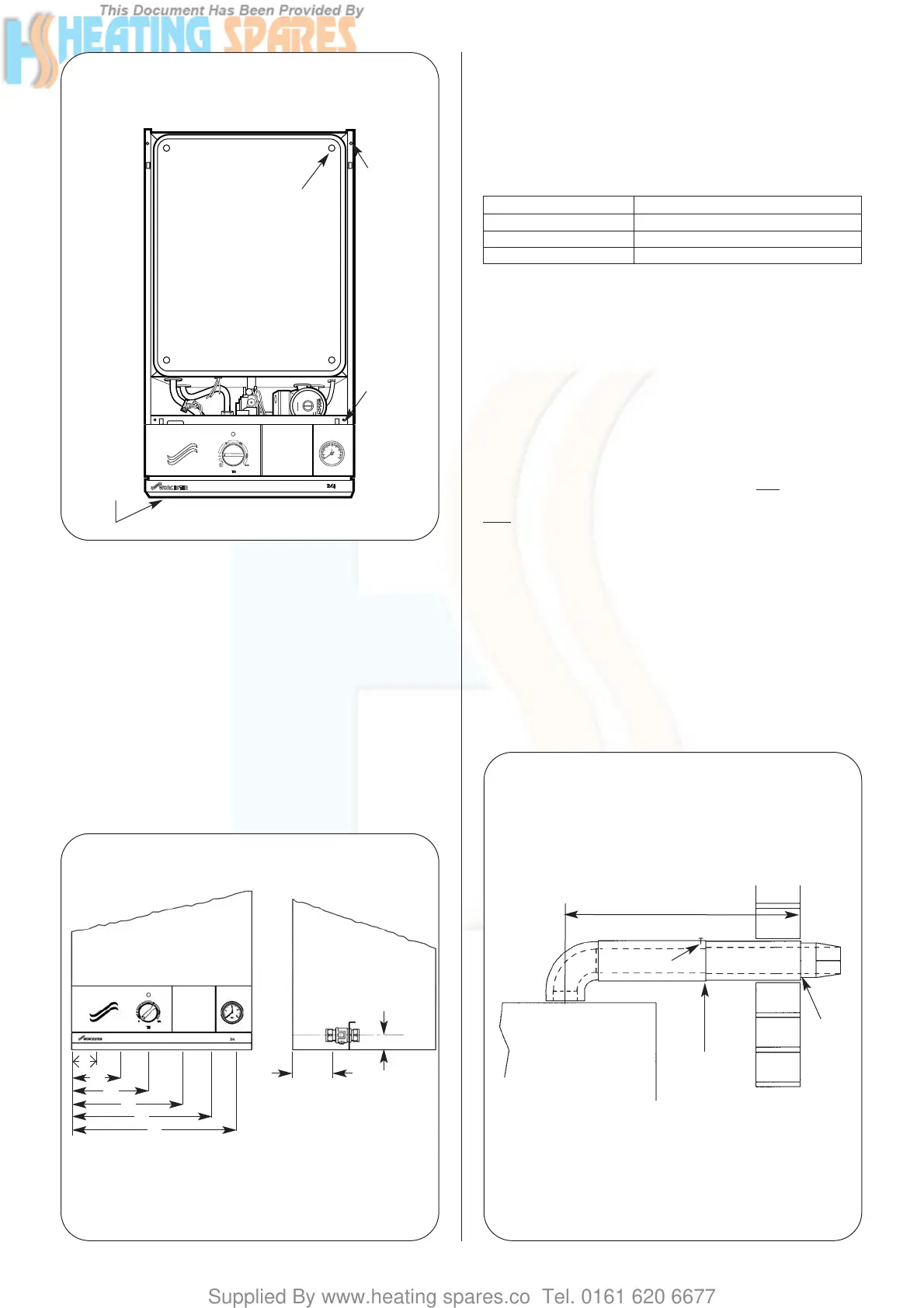
Fig. 13. Appliance pipework connections.
(A)
100mm
36.5mm
(B)
(C)
(D)
(E)
(F)
A Safety Relief = 50mm
B CH Flow = 95mm
C DHW Out = 160mm
D Gas Inlet = 225mm
E Mains Cold Water In = 290mm
F CH Return = 355mm
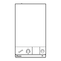
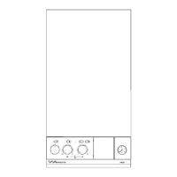
Fig. 12. Appliance casing and control
equipment fixings.
Inner casing
cover
screws (4)
Side casing
fixing
screws (4)
Facia panel
fixing
screws (2)
Bottom facia
panel fixing
screws (3)
Fig.14 . Standard flue assembly.
Appliance casing
Fixing screw
Turret
assembly
Terminal
assembly
L
Telescopic
adjustment