11.13 Vertical Adapter for Horizontal Flues
An adapter is available for an initial short section of vertical flue.
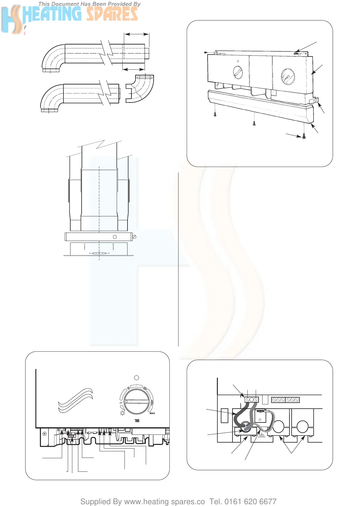
Refer to Fig. 22.
Measure and cut the flue as described in Section 11.12.
The first, vertical, section (equivalent to dimension X) is
measured from the top of the boiler casing. Cut the vertical
section of the extension duct to 167mm less than the measured
distance. Do not remove the socketed ends.
The minimum measured distance is 167mm.
Seal the air duct to the turret using silicone sealant.
Fix the adapter with the clamp and screw provided.
11.14 Completion of the Installation
Check that all the connections on the appliance have been
tightened.
Remove the facia bottom panel. Refer to Fig. 23.
Connect the mains electricity supply lead to the appliance and
secure the cable clamp. Refer to Fig. 23. and 24.
Check there is sufficient loose lead to allow the release of the
facia panel assembly and that the earth lead of the mains supply
cable is longer than the live and neutral leads.
Fit the facia mounted clock. Full instructions are sent with the
programmer.
Connect any external controls ensuring that the leads pass
through the appropriate clamps. Refer to Fig.25.
Test for gas soundness as described in BS6891.
If the appliance is not to be commissioned immediately, replace
the cabinet and facia bottom panel. Check that the gas and
electricity services have been turned off.
If the premises are to be left unoccupied during frosty conditions
then drain the appliance and system. For short inoperative
periods, leave the appliance under the control of the built-in frost
thermostat or the remote frost thermostat (if fitted) or leave
operation continuously with the room thermostat set at 6°C.
15
120mm
100mm
Fig. 21 - Elbow to Flue Turret
Assembly.
Fig. 22 Vertical Adapter.
Flue Duct
Air Duct
Clamp
Adapter
Flue Spigot
Flue Turret
Bend
Fig. 23 - Facia Connections Cover.
1
2
3
4
5
1. Control Panel Fixing Screws
2. Facia
3. Control Panel Pivot Point
4. Connection Cover
5. Connection Cover Fixing
Screws
Fig. 24 -
N. L.
Mains
Fuse 2A Slow Blow
Earth
C
N CI CL
Programmes
R
N RI RL
Room Thermostat
Gas Valve
Fan
Pump
Fig. 25. Mains electricity connections.
Strain relief clamp
Green/yellow
Programmer and room thermostat
strain relief clamps
230V
X1
X2
NL
Blue
Brown