11.1. Mains supply : 230V ~ 50Hz, 180watts. External fuse 3A,
Internal fuses F1 - 2A, F2 - 1.25A (20mm). Spare internal fuses
are supplied with the appliance. Refer to Fig 14.
11.2. The appliance must be earthed. It must be possible to
completely isolate the appliance.
11.3. The mains cable must be 0.75mm2 (24x0.20 mm) to
BS6500-Table 15 or 16.
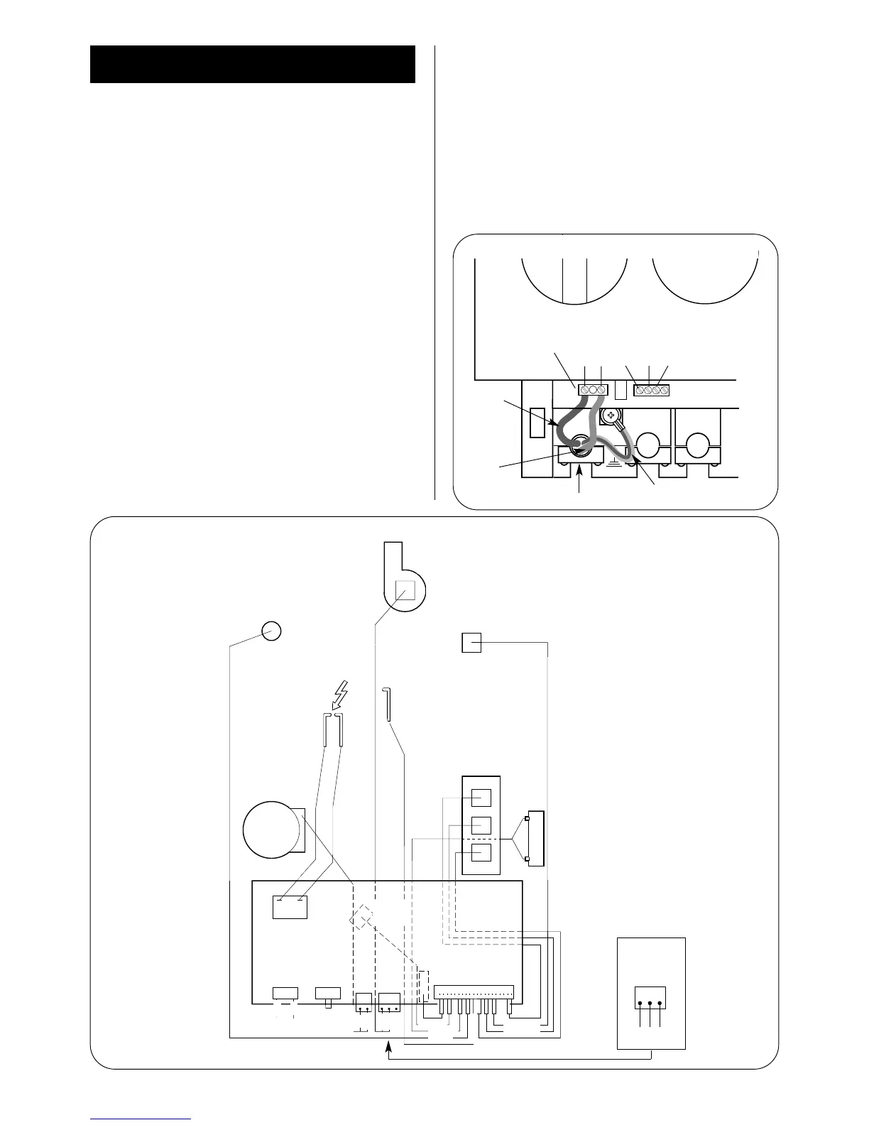
11.4 The mains cable must be connected to the terminal ST12
marked L (red or brown lead), N (black or blue lead ) and the
Earth stud (green or green/yellow lead) and secured with the
cable clamp. Check that sufficient loose lead has been left to
allow access to the control box. The Earth lead must be still be
slack when the other leads are taut. Refer to Fig 8.
11.5. The connection to the mains must be either: A 3A fused
three-pin plug and unswitched socket outlet, both complying with
BS1363 or a double pole isolator with a contact separation of
3mm in all poles and supplying the appliance and controls only.
11.6. Access to the mains connection on the driver board is
gained by removing the bottom cover from the facia. Refer to Fig 12.
11.7. A room thermostat or an externally mounted programmer
must be suitable for mains voltage operation and the leads
securely fixed in the clamps provided. The controls must be
earthed at the connection on the control board. Refer to Fig 11
and 13.
11.8. A choice of programmers, to fit into the facia, are available
to control the CH. Full instructions are sent with the
programmer. Refer to Fig 15.
11.9. On very rare occasions an external frost thermostat might
be considered where parts of the system are remote from the
appliance. Refer to Worcester Heat Systems Technical
Department for more information - Tel: 08705 266241.
11.10. A radio frequency room thermostat is available for use
with the appliance.
11.11.
Safety Check: If there is an electrical fault after
installation check for fuse failure, short circuits, incorrect
polarity of connections, earth continuity or resistance to earth.
10
11. Electrical
Strain relief clamp
Green/yellow
Brown
B
row
n
Blue
Green/yellow
Blue
L
230V
ST12
N Ns LRLS
Fig. 8. Mains electricity connections.
Fig. 9. Wiring diagram.
28CDi
Fan Connections
Black 1
White 4
Red 3
24CDi
Fan
Overheat
cut-off
device
Flame sense
electrode
Air pressure
switch
Spark
electrode
Spark
transformer
Mains in
Link
Control Board
DHW
sensor
Flow
switch
ST16
2 blue
2 orange
2 brown
brown
Blue
brown
yellow
black
white
red
brown
blue
blue
brown
2 violet
white
2 red
2 yellow
2
pink
ST12 ST8
ST15 ST1
ST1
Pump
CH sensor
Gas valve
Reg
Main
2
3
1
Main
2 green
35CDi II
Black 6.3mm tag
White 4.8mm tag
Red 2.8mm tag
28CDi
35CDi
II