The flue system must be installed following the requirements of
BS5440:1.
The standard uncut flue kit length is 425 - 725mm. Extension
kits for flues up to 4m (24CDi), 3m (28CDi and 35CDi
II) are
available.
The terminal must not cause an obstruction nor the combustion
products a nuisance.
A minimum of 75mm must be achieved where the terminal is
near fusible or combustable materials such as a plastic drain
pipe or guttering or carport roof UNLESS suitable heat shields are
provided.
If the terminal is less than 2m above a surface to which people
have access then a guard must be fitted. The guard must be
evenly spaced about the terminal and fixed with plated screws.
A guard Type K2 can be obtained from Tower Flue Components,
Vale Rise, Tonbridge, TN9 1TB.
It is essential that products of combustion cannot re-enter the
building. Refer to Fig 4.
6.1 The appliance does not require a separate vent for
combustion air.
6.2 The appliance can be fitted in a cupboard or compartment
with no vents for cooling but the minimum clearances must be
increased to those given below. (
Note: The clearance at the front is
to removable panel, e.g. a door).
6.3 If the appliance is to be fitted in a cupboard or compartment with
less clearance than those in the table above (minimum clearances are
given in Section 4. Siting The Appliance) then permanent air vents for
cooling are required. One at high level and one at low level, either
direct to outside air or to a room. Both vents must pass to the same
room or be on the same wall to the outside air.
6.4 The minimum free areas required are given below.
6.5 Refer to BS 6798 and BS 5440:2 for additional information.
6. Air Supply5. Siting The Flue Terminal
7
POSITION OF AIR FROM AIR DIRECT
AIR VENTS THE ROOM FROM OUTSIDE
24CDi 28CDi 35CDi
II 24CDi 28CDi 35CDi II
HIGH LEVEL 270 cm
2
315 cm
2
393 cm
2
135 cm
2
158 cm
2
197 cm
2
LOW LEVEL 270 cm
2
315 cm
2
393 cm
2
135 cm
2
158 cm
2
197 cm
2
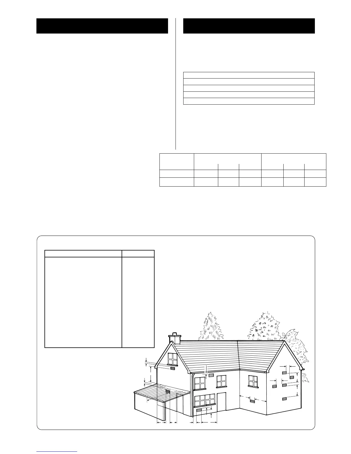
Fig. 4. Siting of the flue terminal.
TERMINAL POSITION MIN. DISTANCE
A– Directly below an openable window or
other opening e.g. air brick. 300 mm
B– Below gutters, soil pipes or drain pipes. 75 mm
C– Below eaves. 25 mm
D– Below balconies or car port roof. 25 mm
E– From vertical drain pipes and soil pipes. 25 mm
F– From internal or external corners. 25 mm
G– Above ground, roof or balcony level. 300 mm
H– From a surface facing a terminal. 600 mm
I– From a terminal facing a terminal 1200 mm
J– From an opening in a car port (e.g. door
window) into dwelling. 1200 mm
K– Vertically from a terminal on the same
wall. 1500 mm
L– Horizontally from a terminal on the same
wall. 300 mm
M– From door, window or air vent . 300 mm
Above the flue turret 30mm
In front 250mm
Below 200mm
Right-hand side 75mm
Left-hand side 75mm
Advice should be taken if the terminal is in close proximity to surfaces which may
bo of plastic materials i.e. car-ports, gutters etc.