18. Water Diverting Valve. See Fig. 36, 40.
Check that the electricity supply to the appliance is turned off.
Drain the central heating and domestic hot water circuits as
described in Sections 16.3, a and b.
Hinge down the facia panel into the Servicing Position as
described in Section 15.3, c.
Remove the bottom panel, filling loop, water to water heat
exchanger and micro switch assembly as described in Section
15.3, d, and Sections 16.4.17, 20 and 22.
Pull off the large wire clip locating the water diverting valve to
the central heating plastic flow manifold on the left hand side of
the appliance.
Remove the wire clip securing the copper by-pass pipe to the
flow manifold.
Retain the wire clips.
Carefully ease the by-pass pipe out of the manifold and allow the
pipe to swing forwards to clear the manifold connection.
Remove the screw securing the bracket, located at the right hand
end of the water diverting valve, to the appliance casing.
Remove the four screws located at the left hand side securing
plastic manifold to the appliance.
Remove the water diverting valve and plastic manifold assembly
clear of the appliance.
Ease the water diverting valve out of the plastic manifold.
Remove the securing bracket from the valve and the water filter
from the valve cold water inlet.
Retain the plastic manifold, fixing screws, support bracket and
water filter.
Discard the water diverting valve.
Reassemble the original support bracket, water filter and new
‘O’ ring seals to the replacement valve.
Lubricate the ‘O’ ring seal and push the plastic flow manifold
onto the valve.
Reassemble the water diverting valve and plastic manifold
assembly to the appliance in the reverse order.
Ensure all ‘O’ ring seals and fibre washers are renewed and
replaced correctly and the ‘O’ rings are lubricated.
Reassemble the appliance in the reverse order.
Open the valves and fill and re-pressurise the system as
described in Section 13.2.
19. Inlet Water Filter. See Fig. 40.
Check that the electric supply to the appliance is turned off.
Drain the central heating and domestic circuits as described in
Sections 16.3, a and b.
Hinge down the facia panel into the servicing position as
described in Section 15.3, c.
Follow the proceedures as described in Section 16.4,18 and
remove the water divering valve from the appliance.
Remove the water filter from the cold water inlet.
Discard or clean the filter.
Fit the replacement filter (push fit) in the reverse order.
Reassemble the appliance in the reverse order.
Open the valves and fill and re-pressurise the system as
described in Section 13.2.
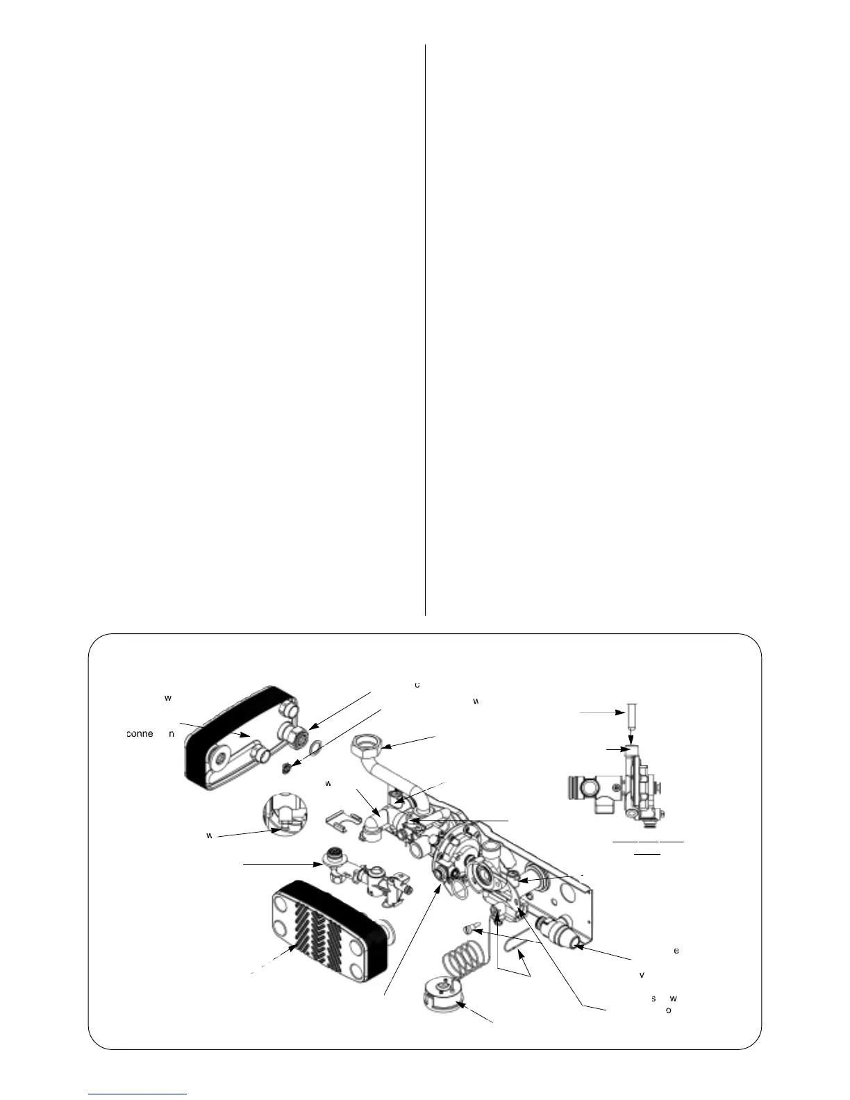
20. Water to Water Heat Exchanger. Refer to Fig. 40.
Check that the electricity supply to the appliance is turned off.
Drain the central heating and domestic hot water circuits as
described in Sections 16.3, a and b.
Hinge down the facia panel into the servicing position as
described in Section 15.3, c.
Remove the bottom panel as described in Section 15.3, d.
Remove the filling loop as described in Section 16.4.22. Undo the
diverter valve connection. Remove the bolt and circlip and pull
the heat exchanger forward and away from the appliance.
Fit the replacement heat exchanger in the reverse order.
Open the valves and fill and re-pressurise the system as
described in Section 13.2.
21. Domestic Hot Water Flow Regulator. Refer to Fig. 40.
Remove the water to water heat exchanger assembly as
described in Section 16.4.20.
The plastic flow regulator is located within the brass housing on
the heat exchanger.
Regulator size:
24CDi 9 l/min white
28CDi 10 l/min blue
35CDi
II 12 l/min red
Fit the replacement flow regulator and reassemble in the reverse
order ensuring the fibre washers and ‘O’ rings are in place.
25
Fig. 40 Filling Loop, Water to Water Heat Exchanger and Domestic Hot Water Flow Regulator