32
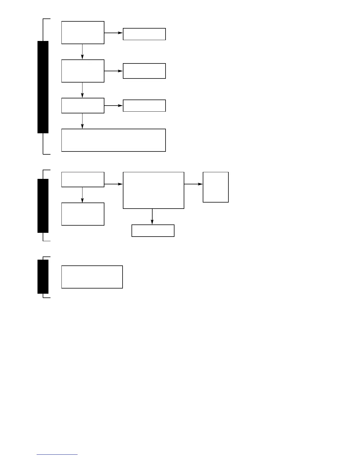
Is the facia on/off
switch turned on?
`(Clockwise)
Is there a 230V AC live
supply across
Terminal ST12 pins L
and N
Has fuse F1 blown?
Replace fuse and investigate cause. Suggestions: Cable
damage, connections to (or faults within) pump, fan,
external 230V controls, transformer or board.
Turn switch on.
Check electrical
supply to boiler.
Replace control board
(Section 16.4.23)
FAIL POINT A
No
No
Yes
Yes
Yes
No
Replace fuse.
This will be caused by
fuse fatigue or by the
board.
Has fuse F2 blown?
Replace
control
board
(Section
16.4.23).
Remove control board from facia
(See Section 16.4.23) and sepa-
rate transformer from board.
Measure resistance across the
two pairs of adjacent pins on the
transformer. Is any pair above
100 ohms?
Replace transformer.
FAIL POINT B
No No
Yes
Yes
Green diode is damaged.
Replace control board.
(Section 16.4.23)
FAIL POINT C