Key
Comfort+ II RF – 6720886122 (2018/07)
16
Once the connection has been established, check the signal
strength at the control unit. If the signal strength is low, try
another position in the room, until the best possible signal
strength is achieved ( Chapter 5.5, page 12).
The functions Pairing and Unpairing can be found in the
installer menu under Radio settings.
To display the installer menu, press menu key and key for
at least three seconds.
Six symbols appear at the top of the display:
• Heating
• DHW
• Holiday
• Information
• settings
• Installer menu
▶ Turn the selector to select the symbol.
▶ Press the selector to open the service menu.
▶ Turn the selector to select Radio settings.
▶ Press the selector.
▶ Turn the selector to select Unpairing or Pairing .
▶ If Pairing is selected, press selector. Pairing is displayed
by a progress bar and the timer starts at 120 s. Once the
connection has been established, the timer is cancelled
and the number of connected control units appears on the
display as confirmation.
-or-
▶ If Unpairing is selected, press selector. Unpairing is
indicated by a progress bar. Once the connection has been
disconnected, "0" appears as confirmation on the display.
7Key
The key is connected to the control unit. Both communicate via
wireless signals. The key has a button and an LED to display
various operating conditions.
7.1 Connecting/disconnecting the control unit
The control unit and key are connected at the factory in the
delivered condition and detect each other automatically
when switching on. It is not necessary to connect/
disconnect unless there is a problem exists with one or both
of the wireless devices.
▶ If a defective wireless device is replaced with a new one, the
defective wireless device must be disconnected before the
new combination can be connected.
▶ In order to connect/disconnect, both wireless devices must
be connected/disconnected.
If a defective wireless device is replaced with a new one, the
defective one must be disconnected before the new wireless
device can be connected. The new wireless device combination
must be connected at the same time.
▶ While the control unit is disconnecting, press the button on
the key for longer than ten seconds to disconnect the key.
The LED flashes five times in five seconds during the
disconnection process.
Once the faulty wireless device has been disconnected, the
new wireless device can be mounted and connected.
▶ While the control unit is connecting, press the button
(Fig. 15, Pos. [2]) on the key briefly to connect the key.
The LED (Fig. 15, Pos. [1]) flashes twice in five seconds
while the connection is being established.
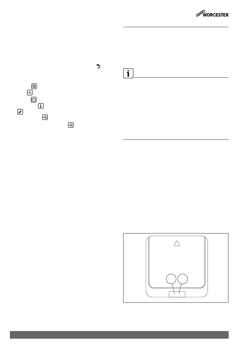
Fig. 15 Key
[1] LED on the key (for the LED coding Table 1)
[2] Button on key
1 2
0010021545-002
 Loading...