PLUMBING MANIFOLD
6 720 645 222a (2012/05)
6
2 PLUMBING MANIFOLD
CONNECTIONS:
• Heating System: 22mm compression fittings
• Gas: 22mm compression fitting
• Cylinder Return 15mm compression fitting
• Use the fittings supplied in the Hardware literature
pack and the Optional Diverter Valve Kit.
If the boiler pipes are to be run behind the appliance
ensure that the pipes pass through the slot in the
guide (9). This is fitted to the boiler frame.
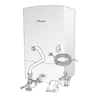
Fig. 1 Pipe dimensions
Fig. 2 Plumbing manifold with wall frame
NOTICE: Fitting the service valve
B Refer to figure 2
B The service valve (7) from the Optional
Diverter Valve Kit must be fitted and
secured to the wall mounting frame with
two screws (8) supplied, before the wall
mounting frame is fitted to the wall.
Further guidance on pipe routing can be
found printed on the boiler template
(supplied with the boiler).
12
3
4
56
6720645222-12.1Wo
# Function
From left
case edge
Diameter
of pipe
1 CH and cylinder flow 70 mm 22 mm
2Gas 200 mm 22 mm
3CH Return 330 mm 22 mm
4Condensate 35 mm 22 mm
5 Pressure Relief Valve 367 mm 15 mm
6 Cylinder return 267 mm 15mm
Tab. 4 Key to figures 1 & 2
1
2
3
6
1
6
2
3
4
5
6720644222-01.1Wo
9
7
8
 Loading...