SERVICING AND SPARES
6 720 812 175 (2014/07) 37
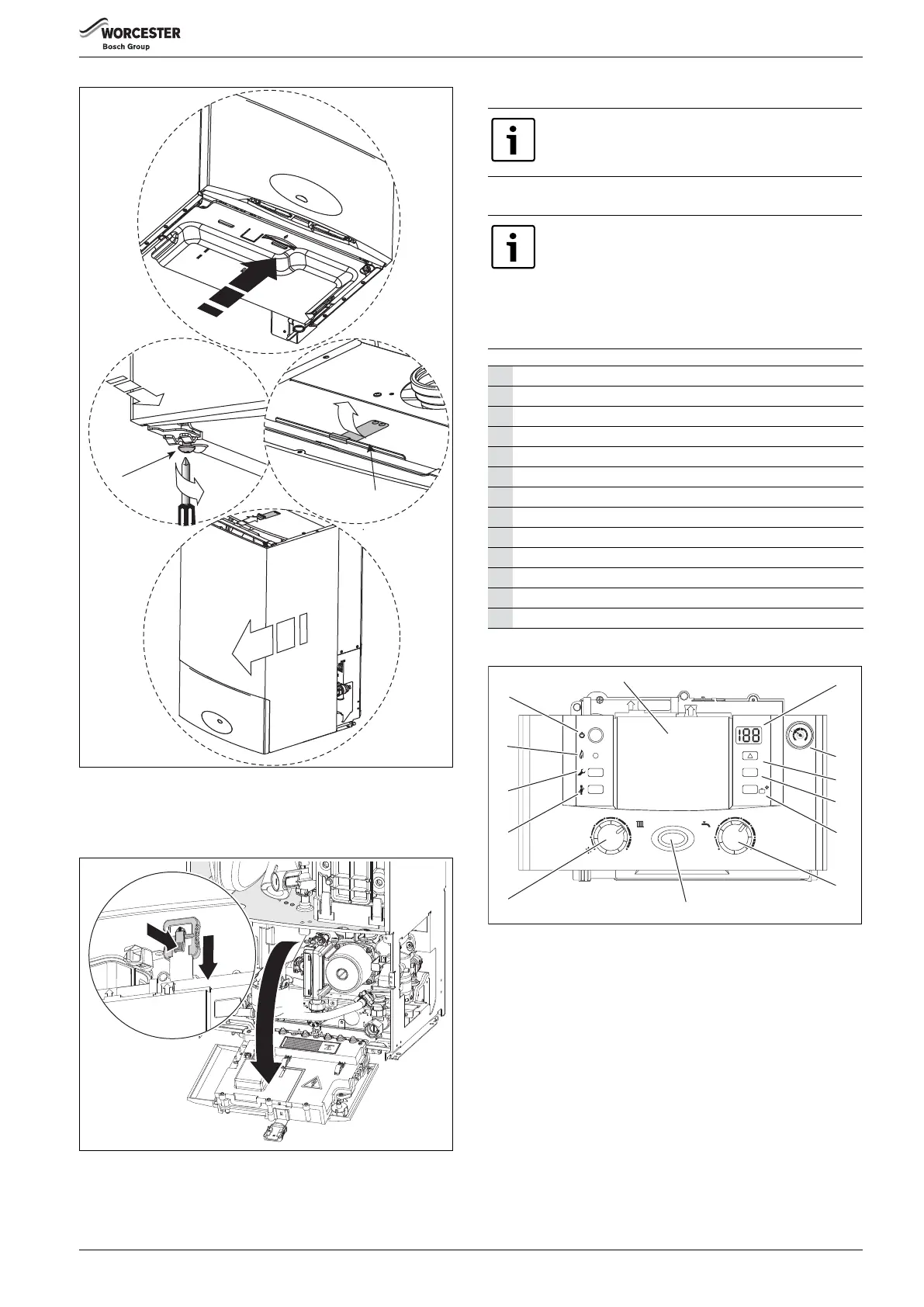
Fig. 57 Removing outer case
2. Adjusting boiler control to service position
1. Squeeze the white clip and pull down to release the control panel.
2. Pull the control panel forward until it comes to rest in service position.
Fig. 58 Controls to service position
6.1.3 FAN PRESSURE TEST
SET THE BOILER TO MAXIMUM
Fig. 59 Control panel
▶ Press and HOLD performance test button (J) for 10 seconds and set
Central Heating temperature to maximum.
– The performance test button will illuminate continually.
– The boiler will stay in this mode for 15 minutes unless the central
performance test button is pressed again.
▶ Pull the cover off and connect a manometer to the fan pressure test
point.
▶ After measurement replace test point cover.
A
B
4.
6720647361-27.4Wo
2.
3.
1.
1.
6 720 812 175-14.1O
2.
This test is to determine if the heat cell requires cleaning/
attention
When fitted with the optional diverter valve (not
supplied) and running in performance test mode, the
boiler will only operate the central heating circuits.
If fitted to an S or Y plan system, the system must only be
run in central heating mode.
This is to allow sufficient time for this part of the
commissioning procedure.
A On/off button
B Cover or position for optional plug-in control
C Display
D System pressure gauge
E Reset button
F ECO button (only with optional diverter valve)
G Holiday button (only in conjunction with optional diverter valve)
H DHW temperature control (only with optional diverter valve)
I Central heating temperature control
J Performance test button
K Service button
L Burner indicator (GREEN)
M On/off and fault indicator (BLUE)
Table 31
1
2
3
4
5
6
max
2
3
1
04
bar
reset
eco
1
2
3
4
e
6
maxmin
A
J
B
K
C
L
D
M
E
F
G
H
I
6720647361-23.2Wo



 To Next Page