SERVICING AND SPARES
6 720 812 175 (2014/07) 41
6.3 REPLACEMENT OF PARTS
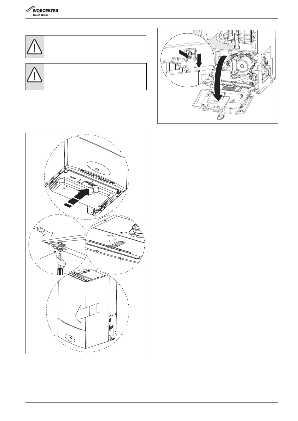
REMOVING OUTER CASE
1. Remove bottom panel by pulling it forward and off.
2. Loosen but do not remove the 2 screws (A) securing boiler casing at
the bottom of the appliance.
3. Pull upwards to release the clip (B) on top of the boiler.
4. Pull case forward and remove.
Fig. 70 Removing outer case
MOVING BOILER CONTROL TO SERVICE POSITION
1. Press in the centre of the white plastic clip securing the control panel
and slide down to release.
2. Pull the control panel forward into the service position.
Fig. 71 Service position
3. PRIMARY SENSOR
▶ Press retaining clip on plastic moulding and pull upwards until clear of
pocket in heat exchanger.
▶ Separate sensor from connector, coat new sensor with heat
conductive paste and replace.
4. OVERHEAT THERMOSTAT
▶ Remove two electrical connectors from thermostat.
▶ Unscrew the sensor.
5. FLUE LIMIT THERMOSTAT
▶ Remove electrical connections.
▶ Push the flue limit thermostat into the sump.
▶ Retrieve the thermostat from the sump well.
6. EXPANSION VESSEL
▶ Drain the appliance.
6.1 Remove locking screw (D).
6.2 Undo the union connection (E) at the bottom of the expansion
vessel.
▶ Remove expansion vessel from boiler.
▶ Set the pressure of the new vessel to that required by the system.
CAUTION: TURN OFF THE GAS SUPPLY AND ISOLATE
THE MAINS SUPPLIES BEFORE STARTING ANY WORK
AND OBSERVE ALL RELEVANT SAFETY PRECAUTIONS.
NOTICE: After replacement of any components always
check for gas tightness where relevant and carry out
functional checks as described in the commissioning
section. Replace any O-rings or gaskets.
A
B
4.
6720647361-27.4Wo
2.
3.
1.
1.
6 720 812 175-14.1O
2.