PRE-
IN STALLATION
INSTALLATION & SERVICING INSTRUCTIONS FOR WORCESTER BOSCH
PRE-
IN STALLATION
INSTALLATION & SERVICING INSTRUCTIONS FOR WORCESTER BOSCH
8-716-106-256a (08.05)
9
WATER SYSTEMS & PIPEWORK
WATER SYSTEMS & PIPEWORK
PRIMARY SYSTEM PLASTIC PIPEWORK:
Any plastic pipework must have a polymeric
barrier with 1000mm (minimum) length of copper
or steel pipe connected to the boiler.
Do not use plastic pipework on sealed systems.
Plastic pipework used for underfloor heating
must be correctly controlled with a thermostatic
blending valve limiting the temperature of the
circuits to approx. 50°C. The pipework from the
boiler to the blending valve must be in copper
or steel (protected from corrosion).
PRIMARY SYSTEM/CONNECTIONS/VALVES:
Do not use galvanised pipes or radiators.
All system connections, taps and mixing valves
must be capable of sustaining a pressure of 3
bar.
Radiator valves should conform to BS2767:10.
All other valves should conform to BS1010.
On new installations TRVs must be used on all
radiators except the radiator where the room
thermostat is sited, this must be fitted with
lockshield valves and left open. All installations
should have TRV's fitted to radiators within the
sleeping accommodation.
An automatic bypass valve must be connected
between the heating flow and return where TRV's
are used on all radiators.
Drain cocks are required at all the lowest points
on the system.
Air vents are required at all high points on the
system.
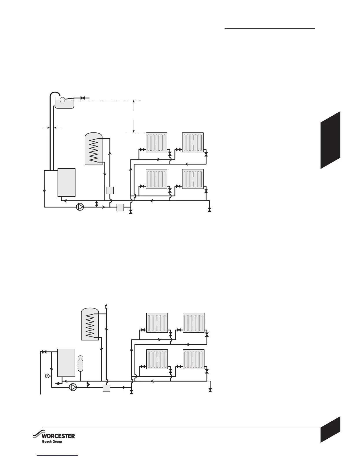
OPEN VENT PRIMARY SYSTEM:
The feed and expansion cistern (E) must be
positioned to provide a static head (S) of at least
1 metre above the highest point in the heating
system to the water level in the feed and
expansion cistern (E).
The heating vent (H) and cold feed (F) pipes
must rise continuously from the appliance.
The heating vent pipe (H) must be at least
22mmØ.
No valve shall be fitted in the open vent pipe (H)
or the feed and expansion pipe (F).
FULLY PUMPED SEALED PRIMARY SYSTEM:
A pressure relief valve (P) (spring loaded safety
valve set to operate at 3 bar) must be fitted to
the heating flow pipe as close as possible to
the boiler or onto one of the boiler top 1" BSP
outlets.
An expansion vessel (B) must be fitted to the
heating return pipe close to the boiler and
pressurised for the system volume according to
the instructions supplied with the vessel.
A pressure gauge (G) (3 bar min.) must be fitted
to the heating flow pipe or one of the boiler 1"
BSP outlets.
An automatic air vent (N) must be fitted.
TYPICAL SEALED SYSTEM:
TYPICAL OPEN VENT SYSTEM:
A - Appliance
B - Expansion vessel
C - Automatic bypass valve
D - Drain cock
E - Feed and expansion cistern
F - Feed and expansion
15mmØ min
G - Pressure gauge
H - Open vent 22mmØ min
J - Circulating pump
K - Zone valve
L - Lockshield valve
M - Hot water cylinder
N - Automatic air vent
P - Pressure relief discharge
R - Radiators
S - Static head
T - TRV
U - To filling system
A
D
R R
R R
B
P
D
C
T
L
T
L
T
L
T
L
E
S
1000mm min.
FH
G
JK
M
N
A
D
R R
R R
D
C
T
L
T
L
T
L
T
L
J
K
M
150mm max.
K
U