Use at own risk when using other generic RS485 dangles.
CAUTION
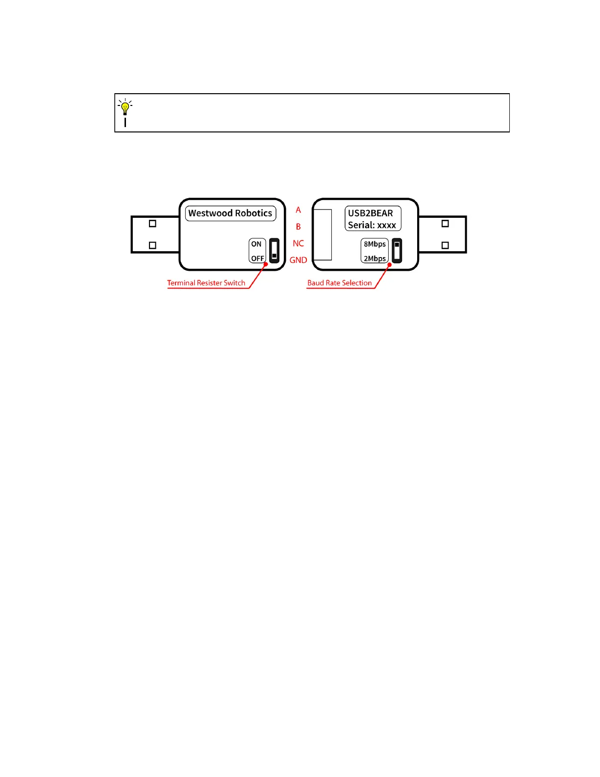
The USB2BEAR dangle is a USB2.0 device and its RS485 connector is a 4-pin Molex Mini-
SPOX 5268 male header. (Mating female housing: 4-pin Molex Mini-SPOX 5264, part num-
ber: 0050375043) It’s pin-out and function of the switches are as shown in fig. 5.
Figure 5: USB2BEAR pin-out and switches.
It is recommended to add a terminal resister of 120 Ohms at the end of RS485 chain when
using long signal cables and the impedance of the signal line is high enough to result in noisy
communication. Put the Terminal Resister Switch at ’ON’ when a terminal resister is applied
at the end of the chain, but be sure to have it at ’OFF’ when no terminal resister is applied
at the end of the chain. USB2BEAR can also be used to communicate with generic RS485
devices other than BEAR. Make sure the matching communication Baud Rate is selected. It
is recommended to use 8Mbps for fast communication when paired with BEARs.
d) Chaining BEAR Signal Ports
When having multiple BEARs in your system, properly chaining their signal lines not only
can make your wire management easy and clean, but also contribute to system reliability
and robustness. Just like all other RS485 devices, you can simply chain your BEARs in a
daisy chain, as shown in fig. 6. It is recommended to add a terminal resistor of 120 Ohm
at the end of the signal chain, especially when the signal line is relatively long or whenever
exceptional signal noise is observed.
There could also be multiple chains of BEARs, such as in the application of dual-arm ma-
nipulators or legged robots. In this type of situation, traditional solutions are either using a
long signal cable to connect the end of one chain with the start of another, or using multiple
RS485 adapters, one for each chain. The former solution could lead to high impedance in
the signal line thus noisy communication, while the latter could result in control complication
and a demand of too many USB ports on the controller.
In the above situations, the unique pass-thru channels on all BEAR signal ports become very
handy. Fig. 7 illustrates a simple example of using the pass-thru channels to achieve a fork
chain. Again, it is recommended to add a terminal resistor of 120 Ohm at the end of the
signal chain, especially when the signal line is relatively long or whenever exceptional signal
noise is observed.
11
 Loading...