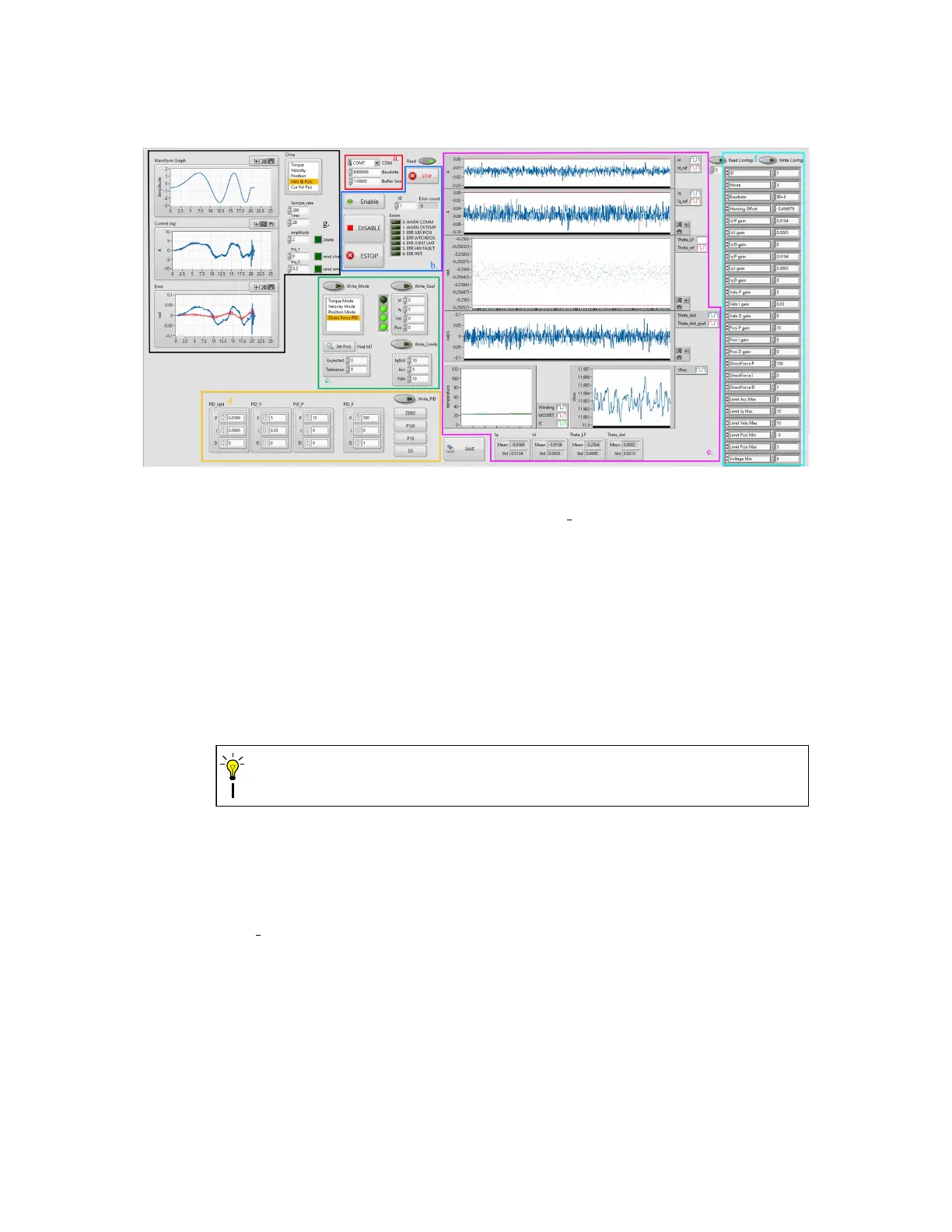
Figure 17: The front panel of Data Ctrl VI.
b. ID, Enable and Error You can chain multiple BEARs and tune them one by one with
the ID setting. You can change the ID while the VI is running. Use the Enable and
DISABLE button to enable/disable the current BEAR and use the ESTOP button to put
the current BEAR into E-stop mode. Use the STOP button to stop the VI. The error
code of the current BEAR is displayed in the ERROR indicator and Error count indicator
displays how many times an error has accrued since the VI started.
c. Mode, Limits and Goals Use this section to write mode, limits and goals to the current
connected BEAR, and you the SAVE button to save the current config register values.
The VI may freeze for a brief second when saving the config registers.
CAUTION
d. PID setting Use this section to change the PID settings of the current connected BEAR.
e. Real-time Status Status of the current connected BEAR is plotted in real-time in this
section, including Excitation Current id, Torque Current iq, Position Theta, Velocity
Theta dot, Temperatures and Present Supply Voltage Vbus.
f. Read Config Click the Read Config button to read all config registers once. Returned
data will be displayed in the indicator. You can also change specific config settings and
hit Write Config button to update the current connected BEAR.
36