BASE UNIT
600 - 1000 Hob
2/3 Drawer
Assembly Guide
For Internal Use: FI.WR.INS.058_WKIN00112_BASE_600-1000_2-3Drw_Hob_Rev1.indd
Page 6
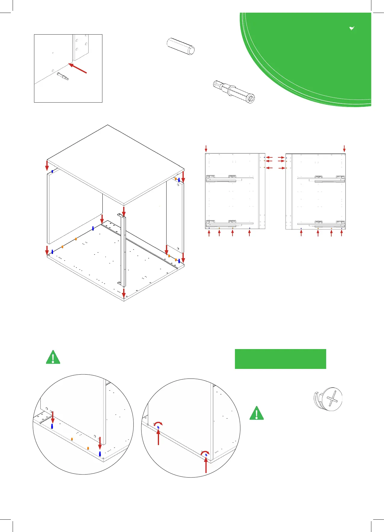
Step 2.
Seat dowel (F) into holes in
both end panels (B) as shown.
Step 3.
Seat cam dowel (G) into holes in
both end panels (B) as shown.
Step 5.
Join panels (C) to (B).
Insert cam lock .
Do NOT tighten until Step 6.
All are to be positioned facing the
outside of the unit carcass, for ease of tightening.
Do NOT use power tools with
cam dowel (G) or cam lock
Seat (G)
cam dowel
into hole as
shown.
B
B
C
B
B
View from underside
View from underside
G
G
Sink Rail
Step 4.
Attach panels (C) & (E) to panels (B), using dowels (F)
(orange) and cam dowel (G) & cam lock (blue) in
positions shown.
Insert sink rails as shown & secure with 2 x 15mm
screws (L) into panels (B).
G
G
G
G
G
F
F
F
F
F
F
B
B
Sink Rail
Insert
Sink Rail
Insert
Dowel (F), Cam Dowel (G)
& Sink Rail Screw
Location detail