S-26
V3307-DI-T-E2B, WSM
ENGINE
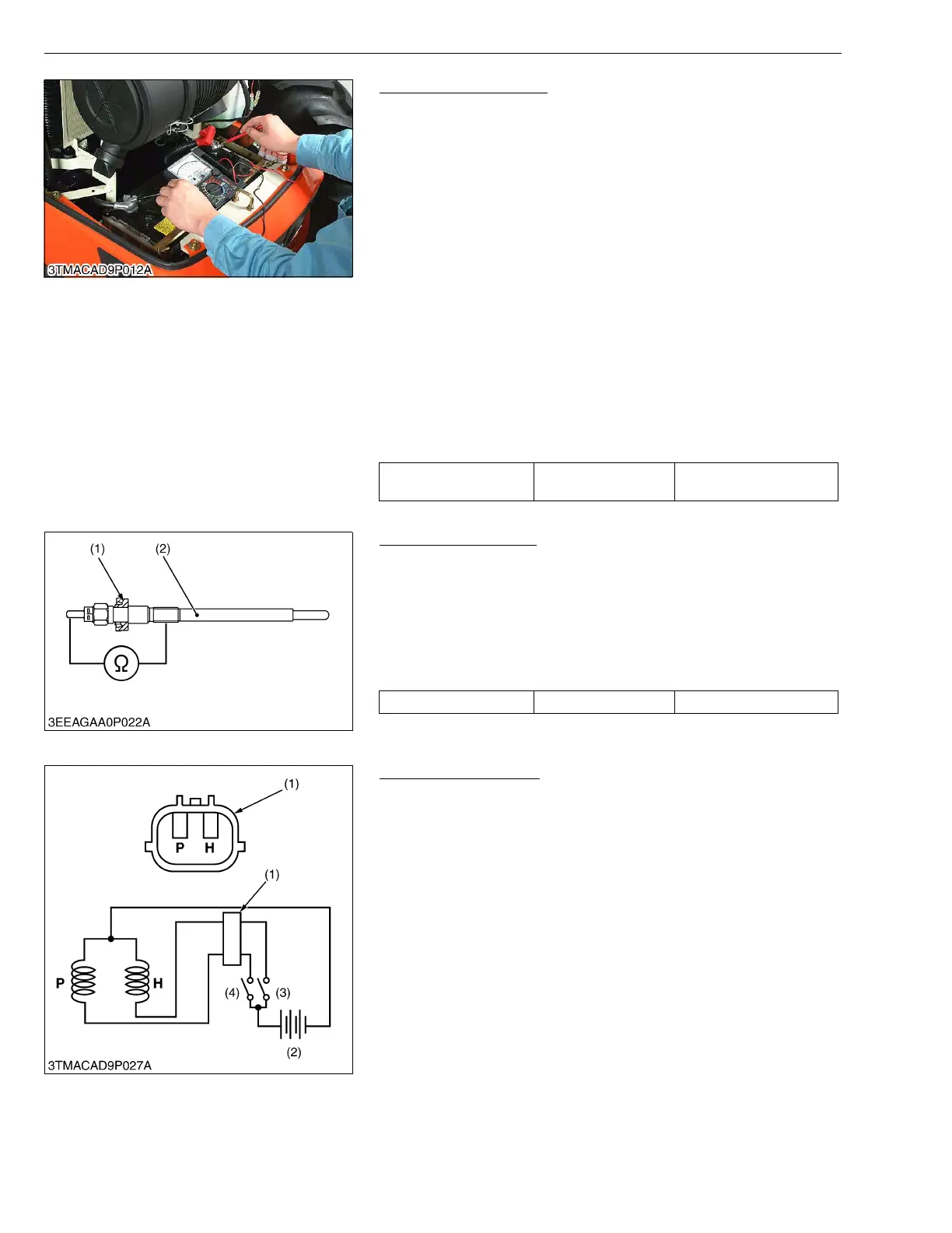
Alternator on Unit Test
(Before testing)
• Before alternator on unit test, check the battery terminal
connections, circuit connection, fan belt tension, charging
indicator lamp, fuses on the circuit, and abnormal noise from the
alternator.
• Prepare full charged battery for the test.
NOTEQ
• Be careful not to touch the rotating engine parts while
engine is running.
Keep safety distance from the engine rotating parts.
1. Start the engine.
2. When the engine is operating measure the voltage between two
battery terminals. If the voltage is between 13.8 V and 14.8 V,
the alternator is operating normally.
3. If the results of alternator on unit test are not within the
specifications, disassemble the alternator and check the each
component part for finding out the failure. See the
“DISASSEMBLING AND ASSEMBLING” and “SERVICING” for
alternator.
0000010745E
Glow Plug Continuity
1. Remove the glow plug (2).
2. Measure the resistance with a circuit tester between the glow
plug terminal and the glow plug housing.
3. If the factory specification is not indicated, glow plug (2) is faulty.
NOTEQ
• Adjust the direction of the ditch to the terminal side when
the seal (1) is installed in the glow plug (2).
W1036945
Engine Stop Solenoid
1. Remove the engine stop solenoid from the engine.
2. Connect the jumper leads from the pulling coil P terminal to the
switch (3), and from switch (3) to the battery positive terminal.
3. Connect the jumper leads from the holding coil H terminal to the
switch (4), and from switch (4) to the battery positive terminal.
4. Connect the jumper leads from the engine stop solenoid body to
the battery negative terminal.
5. When switch (4) is turn on, the plunger pull into the solenoid body
and then turn off the switch (4), the plunger comes out.
6. Turn on the switch (3) then turn on the switch (4), the plunger pull
into the solenoid body and it keep in holding position after turn off
the switch (4).
7. If the plunger is not attracted, the engine stop solenoid is faulty.
IMPORTANTQ
• Never apply the current for pulling coil more than two
seconds when inspecting.
W1020600
Regulating voltage at no
load
Factory spec.
13.8 to 14.8 V at
25 °C (77 °F)
Resistance Factory spec. Approx. 0.95 Ω
(1) Seal (2) Glow Plug
(1) Connector
(2) Battery
(3) Switch for Holding Coil
(4) Switch for Pulling Coil
P : Terminal for Pulling Coil
H : Terminal for Holding Coil



 To Next Page