Model 2000 Stepper
3.
ADJUSTMENTS
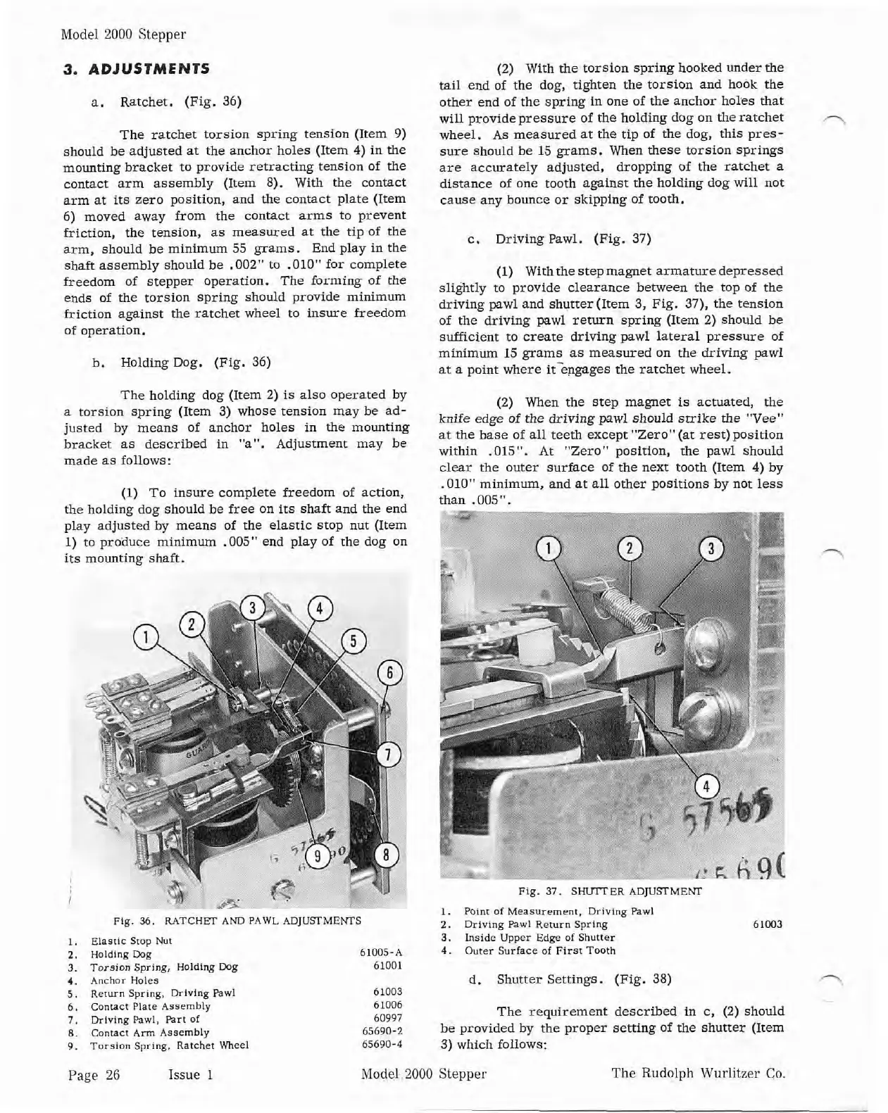
a. Ratchet. (Fig. 36)
The ratchet torsion spring tension (Item
9)
should be adjusted at the anchor holes (Item
4)
in the
mounting bracket to provide retracting tension of the
contact arm assembly (Item 8). With the contact
arm at
its
zero position, and the contact plate (Item
6) moved away from the contact arms to prevent
friction, the tension, as measured at the tip of
the
arm, should be minimum 55 grams. End play in the
shaft assembly should be
.002" to .010" for complete
freedom of stepper operation. The forming of the
ends of the torsion spring should provide minimum
friction against the ratchet wheel to insure freedom
of operation.
h. Holding Dog. (Fig. 36)
The holding dog (Item 2)
is
also operated
by
a torsion spring (Item
3)
whose tension may he ad-
justed by means of anchor holes in the mounting
bracket as described in "a". Adjustment may be
made as follows:
(1)
To insure complete freedom of action,
the holding dog should be free on its shaft and the end
play adjusted
by means of the elastic stop nut (Item
1) to
prorluce minimum .005" end play of the dog on
its mounting shaft.
Flg.
36.
RATCHET
AND
PAWL
ADJUSMEiWS
I.
Eias~ic
Srop
Nut
2.
Holding
Dog
3.
Torsion Spring, Holdlng Dag
4.
Anchor
Holes
5.
Rerurn
Spring, Drhlng Pawl
6.
Contact Piare Assembly
7.
Driving Pawl, Part
of
8.
Contact
Ann
Assembly
9.
Torslon
Spring. Ratchet Wheel
(2) With the torsion spring hooked under the
tail end of the dog, tighten the torsion and hook
the
other end of the spring in one of the anchor holes that
will provide pressure of the holding dog on the ratchet
wheel. As measured at the tip of the dog, this pres-
sure should be 15 grams. When these torsion springs
are accurately adjusted, dropping of the ratchet a
distance of one tooth against the holding dog will not
cause any bounce or skipping of tooth.
c. Driving Pawl. (Fig. 37)
(1) With the step magnet armature depressed
slightly to provide clearance between the top of the
driving pawl and shutter (Item 3, Fig.
37). the tension
of the driving pawl return spring (Item 2) should be
suflicient to create driving pawl lateral pressure of
minimum 15 grams as measured on the driving pawl
at a point where it-engages the ratchet wheel.
(2)
When the step magnet
is
actuated, the
knife edge of the driving
pawl should strike the "Vee"
at the base of all teeth except "Zero" (at
rest)position
within .015". At "Zero" position, the pawl should
clear the outer surface of the next tooth (Item
4)
by
.010" minimum, and at all other positions by not less
than
.005".
Fig.
37.
SHVlTER
ADJUSTMENT
1.
Point
of
Measurement.
Driving Pawl
2.
Drlving Pawl
Return
Spring
61W3
3.
Inside
Upper
Edge
of
Shutter
4.
Outer
Surface
of
First Tooth
d. Shutter Settings. (Fig. 38)
n,
The requirement described in c, (2) should
be provided by the proper setting of the shutter (Item
3) which follows:
Page
26 Issue 1 Model 2000
Stepper The Rudolph
Wurlitzer Co


 To Next Page