Model 5210 Wall Box
q.
When a dime
is
accepted
by
the slug rejector,
it will drop on the longest (or center section) of the
coin paddle as shown in Figure
8.
The coin feeler
and
lever assembly will intercept the ten cent coin
counter disc and position the coin counter wheel as
determined by the setting of the ten cent coin counter
disc.
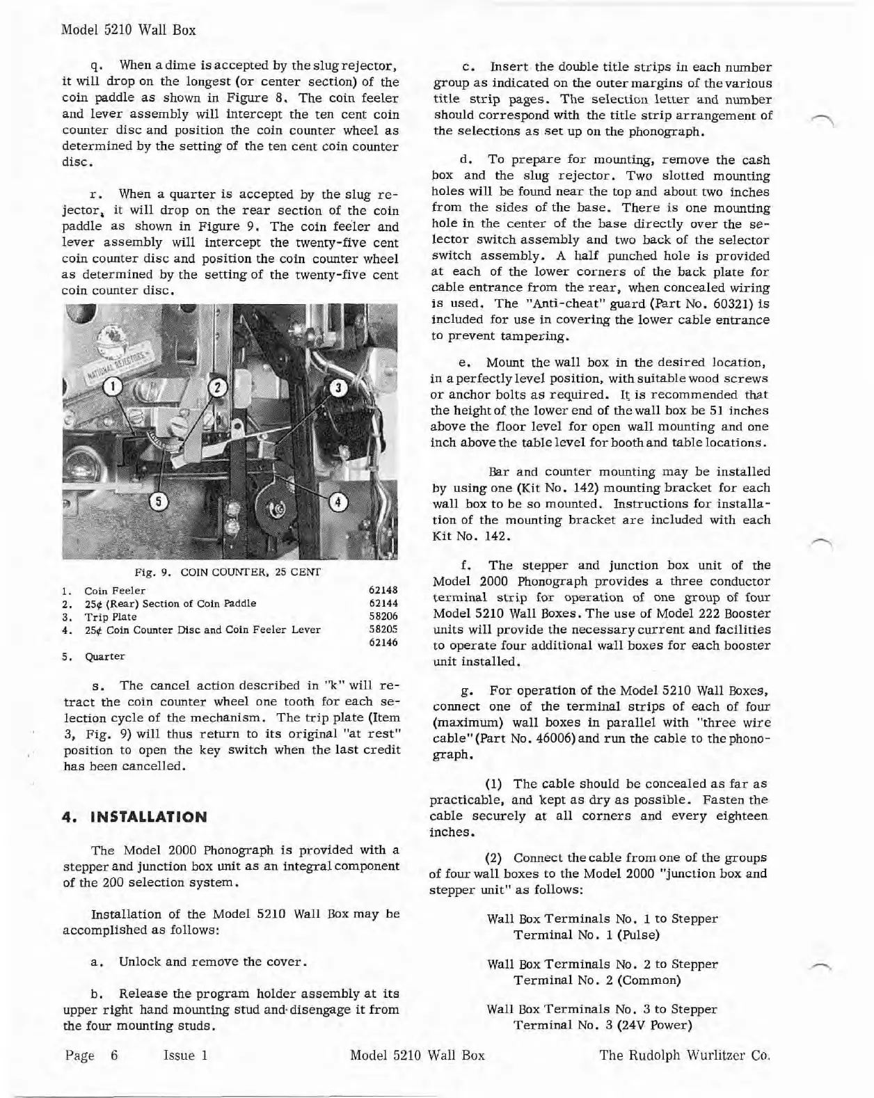
r.
When a quarter
is
accepted by the slug re-
jector, it will drop on the rear section of the coin
paddle as shown in Figure
9.
The coin feeler and
lever assembly
will
intercept the twenty-five cent
coin counter disc and position the coin counter wheel
as determined by the setting of the twenty-five cent
coin counter disc.
e.
Mount the wall box
in
the desired location,
in aperfectly level position, with suitable wood screws
or anchor bolts as required.
It
is
recommeruled that
the height of the lower end of the wall box he 51 inches
above the floor level for open wall mounting and one
inch above the table level for
boothand table locations.
Bar and counter mounting may be installed
by using one (Kit No. 142) mounting bracket for each
wall box to he so mounted. Instructions for installa-
tion of the mounting bracket are included with each
Kit No. 142.
A
Pig.
9.
COIN COWER.
25
CENT
1. Coin
Feeler
62148
2.
250
(Rear)
Section of Coin
Paddle
62144
3.
Trip Plate 58206
4.
25$
Coin Counter
Msc
and
Coin
Feeler
Lever
58202
62146
5.
Quarter
s.
The cancel action described in
"k"
will re-
-act the coin counter wheel one tooth for each se-
lection cycle of the mechanism. The trip plate (Item
3,
Fig.
9)
will thus return to its original "at rest"
position to open the key switch when the last credit
has been cancelled.
4.
INSTALLATION
c. Insert the double title strips in each number
group as indicated on the outer margins of thevarious
title
strip pages. The selection letter and number
should correspond with the title strip arrangement of
,-,
the selections as set up on the phonograph.
d.
To prepare for mounting,
remove the cash
box and the slug rejector. Two slotted mounting
holes will be found near the top and about two inches
from the sides of the base. There
is
one mounting
hole in the center of the base directly over the se-
lector switch assembly and two hack of the selector
switch assembly.
A
half punched hole
is
provided
at each
of the lower corners of the back plate for
cable entrance from the rear, when concealed wiring
is
used. The "Anti-cheat" guard (Part No. 60321)
is
included for use in covering the lower cable entrance
to prevent tampering.
f.
The stepper and junction box unit of the
Model 2000 Phonograph provides a three conductor
terminal strip for operation of one group of four
Model 5210 Wall Boxes. The use of Model 222 Booster
units will provide the necessary current and facilities
to operate four additional wall boxes for each booster
unit installed.
g.
For operation of the Model 5210 Wall Boxes,
connect one of the terminal strips of each of four
(maximum) wall boxes in parallel with
"three wire
cableW(Part No. 46006)and run the cable to thephono-
graph.
(1)
The cable should be concealed as far as
practicable, and kept as dry as possible. Fasten the
cable securely at all corners and every eighteen
inches.
The Model 2000 Phonograph
is
provided with a
(2)
Connect the cable from one of the groups
stepper and junction
box unit as an integral component
of four wall boxes to the Model 2000 "junction box and
of the 200 selection system.
stepper unit" as follows:
Installation of the Model 5210 Wall Box may be
Wall Box Terminals No.
1
to Stepper
accomplished as follows:
Terminal No.
1
(Pulse)
a.
Unlock and remove the cover.
Wall Box Terminals No. 2 to Stepper
Terminal No. 2 (Common)
b.
Release the program holder assembly at
its
upper right hand mounting stud and.disengage it from
Wall Box Terminals No. 3 to Stepper
the four mounting studs.
Terminal No.
3
(24V Power)
Page
6
Issue 1
Model 5210 Wall Box The Rudolph
Wurlitzer
Co.
 Loading...