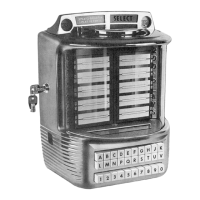
Model 5210 Wall Box
3.
OPERATION
c. The selector switch lock component of the
"cam and hub assembly, counter wheel" (Item
2,
Fig.
The Model
5210
Wall Box
is
mechanically operat-
5)
is
the next to function by releasing the "arm, hub,
ed by its drive motor (Item
2,
Fig. 4), through one
and roller assemhly" just enough to permit latching
complete cycle of operation for each selection made,
of the selector switches. The "lock
bar and adjustinp
-
screw assemhly"(1tem
1,
Fig. 3)is actuated bymove-
ment of the arm (Item 6) to produce the latching action
described above.
d. The next action will he produced, again, by
the "cam, hub, and pin assembly" (Item
5,
Fig. 6)
to actuate the "lifter lever assembly" (Item 7) and the
"coin feeler and lever assembly" (Item 6). This action
moves the coin feeler (Item 1) across the three coin
exits of the slug rejector and the feeler therefore
is
intercepted in one of three different positions. The
opposite end of the "feeler and lever" (Item
8)
is
thus
positioned
in
one of three different planes to engage
the "coin counter wheel and plate assemhly" (Item
9).
e.
As
the cycle advances, the "cam and hub as-
semblyV(Item
2,
Fig.
5)
again acts to further release
the button latch bar and produce complete locking of
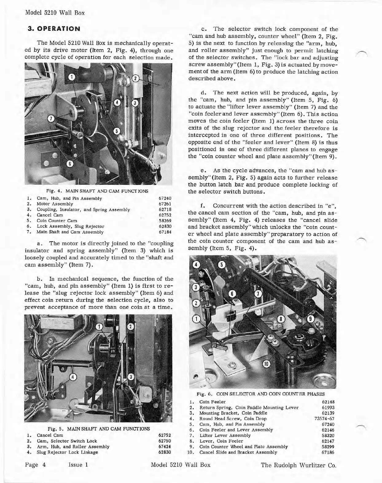
fig. 4.
MA~N
SHAFT AND
CAM
FUNCTIONS
the selector switch buttons.
1. Cam. Hub, and
Pln
Assemblv 67240
2. Motor Assembly 67261
f. Concurrent with the action
described
in "em,
3.
Coupling,
Insulator, and Spring Assembly 62718
4. Cancel
am
62752
the cancel cam section of the "cam, hub, and pin
as-
5. Coln Counter Cam 58269
sembly" (Item
4,
Fig. 4) releases the "cancel slide
6. Lock Assembly, Slug Relector 62830
and bracket assemb1y"which unlocks the "coin count-
7.
Maln
Shaft and Cam' Assembly
67184
er wheel and plate assemblyVpreparatory to action of
a.
~h~
motor
is
directly joined
to
the
~~~~~li~~
the coin counter component of the cam and hub as-
insulator and spring assembly" (Item
3)
which is
sembly
(Item
5s
Fig. 4).
.
-
.
.
loosely coupled and accurately timed to the "shaft and
cam assemhly" (Item 7).
b.
In
mechanical sequence, the function of the
"cam, hub, and
ptn assembly" (Item
1)
is
first to re-
lease the "slug rejector lock assembly" (Item 6) and
effect coin return during the selection cycle, also to
prevent acceptance of more than one coin at a time.
Fig.
5.
MAlN SHAm
AND
CAM FUNCTIONS
I.
Cancel Cam
2. Cam, Selector Switch
Lock
3.
Arm,
Hub,
and
Roller Aasembly
4. Slug Rejector Lack Llnkage
Pig. 6. COlN SELECTOR AND COlN COUNTER PHASES
I.
Coin Feeler 62148
2.
ReNrn Spring. Coin Paddle Mounting Lever 61993
3. Mounting Bracket.
Coin Paddle
62139
4. Round Head Screw, Coin
Drop
73574-67
5. Cam,
Hub,
and
Pin
Assembly
67240
6. Coin Feeler and
Lwer Assembly
62146
62752 7. Lifter Lever Assembly 58320
62750 8. Lever. Coin Feeler 62147
67424 9.
Coin Counter Wheel and Plate Assembly 58299
62830 10. Cancel Slide and Bracket Assembly 67186
Page
4 Issue
1
Model 5210 Wall Box
The
Rudolph Wurlitzer Co.


 To Next Page